Supercharge Your Innovation With Domain-Expert AI Agents!

Rotating control mechanism of shutter louver

a control mechanism and shutter technology, applied in the direction of building components, constructions, buildings, etc., can solve the problems of inapplicability to shutters, elastic fatigue, hole strip wear, etc., to prevent the louver from cracking and reduce production and manufacturing costs

Inactive Publication Date: 2010-07-15
NIEN MADE ENTERPRISE CO LTD
View PDF7 Cites 4 Cited by
  • Summary
  • Abstract
  • Description
  • Claims
  • Application Information

AI Technical Summary

Benefits of technology

[0012]The present invention is also directed to only pushing the louver towards a major axis direction with a greater thickness after inserted with the rotating control mechanism, so as to prevent the louver from cracking when pushed towards a minor axis direction with a smaller thickness.
[0013]The present invention is further directed to only replacing one of the components instead of the whole rotating control mechanism when changing new parts, so as to reduce the production and manufacturing cost.
[0018]Therefore, through the above structure, when the rotating control mechanism is assembled on the louver, a thrust is applied on the major axis direction with the thicker thickness of the louver, so as to prevent the louver from cracking resulting from applying the thrust in the minor axis direction of the louver with the thinner thickness. During the part replacement, only one of the components, for example, the anchor made of a plastic material and / or the bush, is replaced, so as to reduce the production and manufacturing cost.

Problems solved by technology

Though this tension screw assembly mechanism provides an infinite adjustment range of the louver position, it is inapplicable to shutters with hole strips adapted to assemble the louvers on the shutter.
That is, after a long-time usage, the hole strip may be worn, and the frictional force cannot balance the weight making the louver rotate to the closing state.
Moreover, when the spring is kept in the same compression state for an excessively long time, the elastic fatigue occurs, and the elasticity decreases accordingly.
Thereby, the thrust on the countersunk screw and the counterbored hole of the frame is relatively reduced, and the louver cannot be placed at the required position.
At this point, if the countersunk screw is further locked in, the louver may crack.
Especially when made of a medium density fiber (MDF) board, the louver is more easily damaged.
However, after a long-time usage, and when the frictional force therebetween is reduced, the wooden screw is further locked in.
Although the normal force on the louver is increased, the louver may be bent due to over-push, such that the opening or closing action is not smooth and a light leak occurs, or the louver is broken, or the thread of the wooden screw is damaged.
If the replacement is to be performed, the whole louver assembly, louver pin, or frame must be replaced, and the cost is quite high.

Method used


Image

  • Rotating control mechanism of shutter louver
  • Rotating control mechanism of shutter louver
  • Rotating control mechanism of shutter louver

Examples


Embodiment Construction

[0030]An embodiment of the present invention is illustrated in detail below with the accompanying drawings.

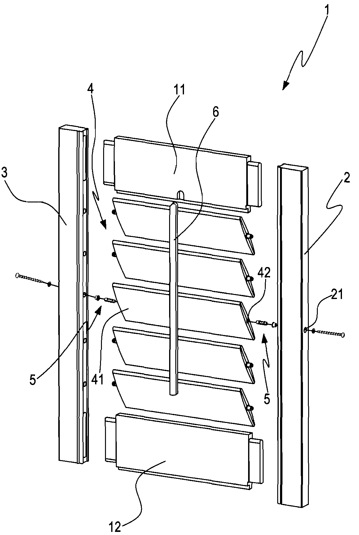
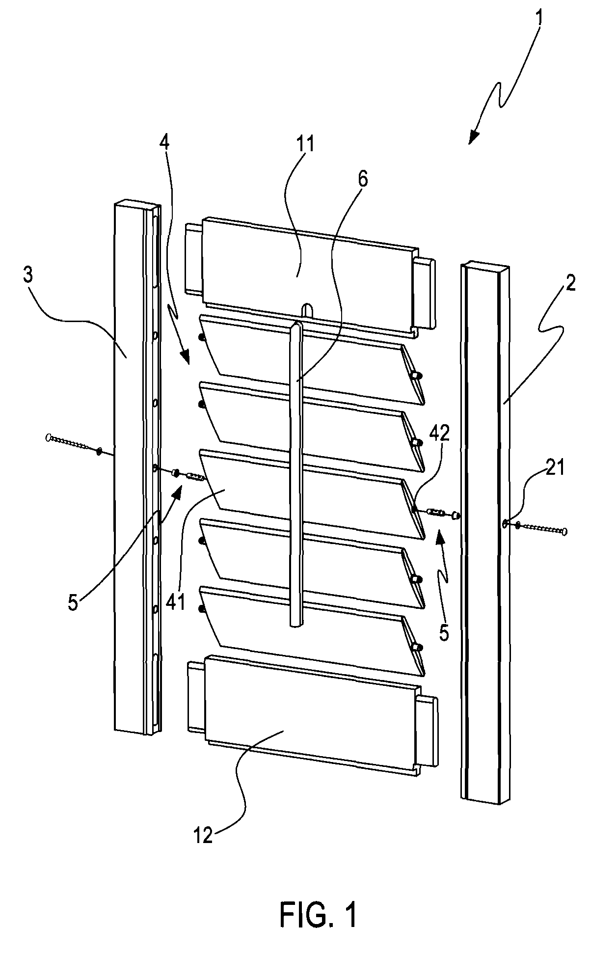
[0031]FIG. 1 is an exploded view of a shutter according to an embodiment of the present invention. A shutter 1 of the present invention includes a top rail 11, a bottom rail 12, two stiles 2 and 3, a louver assembly 4, a rotating control mechanism 5, and a control rod 6.

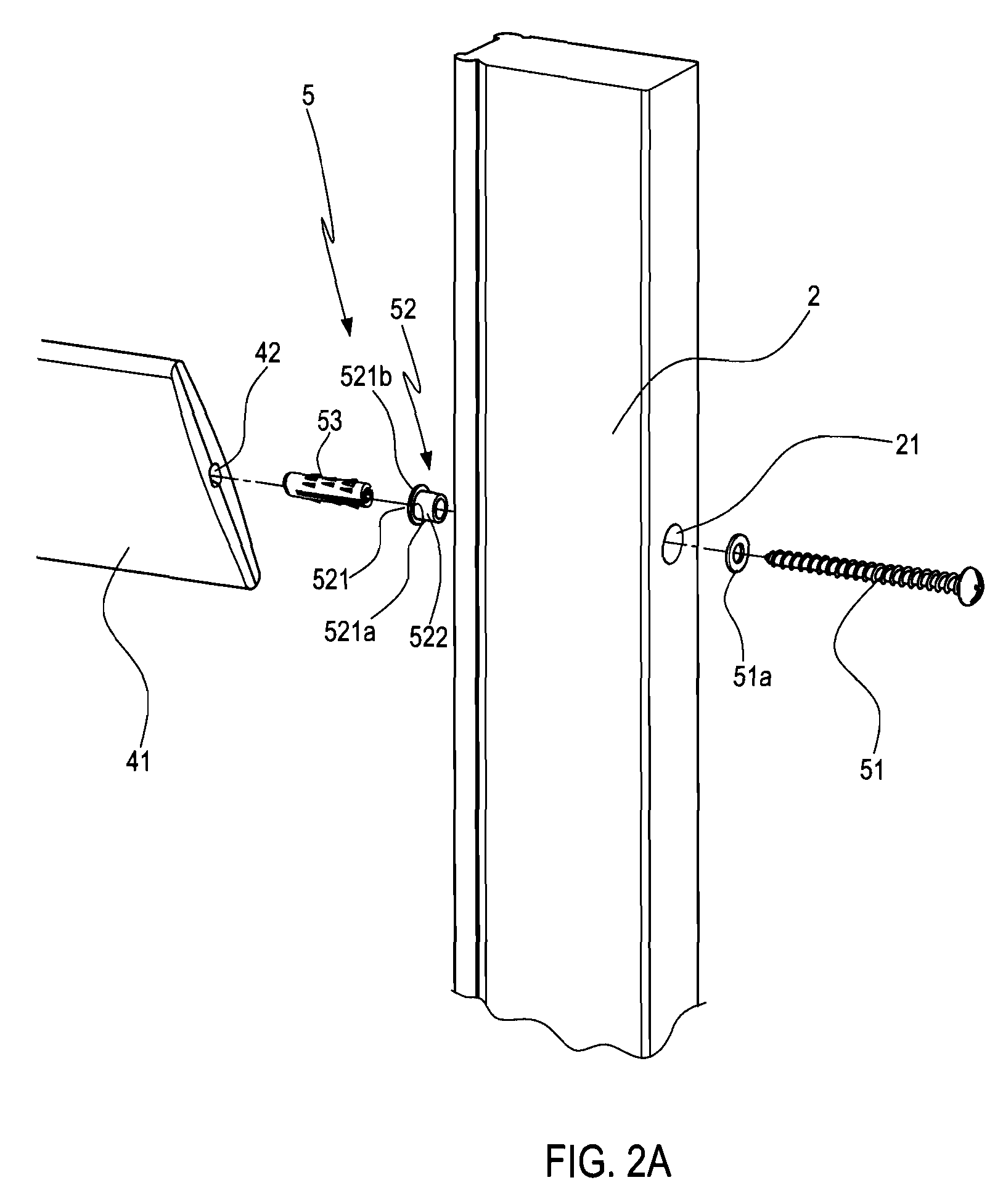
[0032]The two stiles 2 and 3 spaced by a predetermined distance and disposed in parallel are joined to the top rail 11 and the bottom rail 12. The louver assembly 4 composed of a plurality of louvers 41 is disposed between the two stiles 2 and 3. The louvers 41 are sequentially disposed in parallel from top to bottom (as shown in FIG. 1), and an axial direction of the louver 41 is perpendicular to that of the stiles 2 and 3. Moreover, an axial hole 42 is respectively formed on end surfaces of each louver 41 facing the two stiles 2 and 3, and the rotating control mechanism 5 is disposed between the stiles 2 and 3...


PUM


Abstract

A rotating control mechanism of the shutter louver is disposed at a louver and includes an anchor, a bush, and a screw. The anchor has an opening end and a closed end, so as to form a first separating portion and a second separating portion respectively corresponding to a major axis in a radial direction of the louver. The bush has a cylinder portion neighboring to the frame and embedded in the counterbored hole of the frame, and an annular flange attached to the frame and the louver and / or the opening end of the anchor with both sides respectively. The screw passes through the counterbored hole and the bush in sequence to lock the anchor, such that the anchor moves towards the major axis direction of the louver and stops at a screw on an inner surface of the axial hole, so as to prevent the louver from cracking.

Description

BACKGROUND OF THE INVENTION[0001]1. Field of Invention[0002]The present invention relates to a rotating control mechanism of a shutter louver, and more particularly to a rotating control mechanism, in which two ends of a louver are pulled outwards, and a thrust for assembling the rotating control mechanism in an axial hole of the louver is only applied along a major axis in a radial direction of the louver, thereby preventing the louver from cracking and damaging due to the stress along the minor axis in the radial direction of the louver, and only one of the components needs to be replaced when changing new parts so as to reduce the cost.[0003]2. Related Art[0004]In a common shutter, a pin is usually pivoted between each louver and the frame, such that the louver is able to pivotally rotate about the frame and fixed at a preset position, so as to control the opening angle of each louver.[0005]In US Patent Publication No. US6865847, a tension screw assembly mechanism is provided for...

Claims


Application Information

Patent Timeline
IPC IPC(8): E06B7/086E06B7/084
CPCE06B7/086
Inventor CHEN, LIN
Owner NIEN MADE ENTERPRISE CO LTD
Features
  • R&D
  • Intellectual Property
  • Life Sciences
  • Materials
  • Tech Scout
  • Unparalleled Data Quality
  • Higher Quality Content
  • 60% Fewer Hallucinations
Learn More