Evaporator unit

a technology of evaporator unit and evaporator, which is applied in the direction of refrigeration machines, compression machines with several evaporators, lighting and heating apparatus, etc., can solve the problems of deteriorating mounting performance of the refrigerant cycle device to a vehicle, and achieve the effect of improving the mounting performance of the refrigerant cycle device including the evaporator uni

Inactive Publication Date: 2010-07-15
DENSO CORP
View PDF9 Cites 24 Cited by
  • Summary
  • Abstract
  • Description
  • Claims
  • Application Information

AI Technical Summary

Benefits of technology

[0008]It is another object of the present invention to provide an evaporator unit in which plural components are integrally assembled for a refrigerant cycle device, thereby improving mounting performance of the refrigerant cycle device.
[0009]According to an aspect of the present invention, an evaporator unit for a refrigerant cycle device includes: an ejector that is provided with a nozzle portion configured to decompress refrigerant and a refrigerant suction port from which, refrigerant is drawn by a high-speed refrigerant flow jetted from the nozzle portion, and is configured such that the refrigerant jetted from the nozzle portion and the refrigerant drawn from the refrigerant suction port are mixed and the mixed refrigerant is discharged from an outlet of the ejector; a first evaporator coupled to the outlet of the ejector to evaporate the refrigerant flowing out of the outlet of the ejector; a second evaporator coupled to the refrigerant suction port to evaporate the refrigerant to be drawn into the ejector from the refrigerant suction port; a flow amount distributor that is connected to a refrigerant inlet side of the nozzle portion, is located at a position upstream of the second evaporator in a refrigerant flow, and is configured to adjust a flow amount of the refrigerant distributed to the nozzle portion and a flow amount of the refrigerant distributed to the second evaporator; and a throttle mechanism provided between the flow amount distributor and the second evaporator to decompress the refrigerant flowing into the second evaporator. In the evaporator unit, the ejector, the first evaporator, the second evaporator, the flow amount distributor and the throttle mechanism are assembled integrally. The flow amount distributor is adapted as both of a gas-liquid separation portion separating the refrigerant flowing therein into gas refrigerant and liquid refrigerant, and a refrigerant distribution portion for distributing the separated refrigerant into the nozzle portion and the second evaporator. Furthermore, in the evaporator unit, the flow amount distributor and the ejector are arranged in line in a longitudinal direction of the ejector. Accordingly, mounting performance of the refrigerant cycle device including the evaporator unit can be improved.

Problems solved by technology

However, JP 2007-46806A does not describe regarding the assemble structure of the components in the refrigerant cycle device, and, thereby mounting performance of the refrigerant cycle device to a vehicle may be deteriorated based on the assemble structure of the components.

Method used


Image

  • Evaporator unit
  • Evaporator unit
  • Evaporator unit

Examples


first embodiment

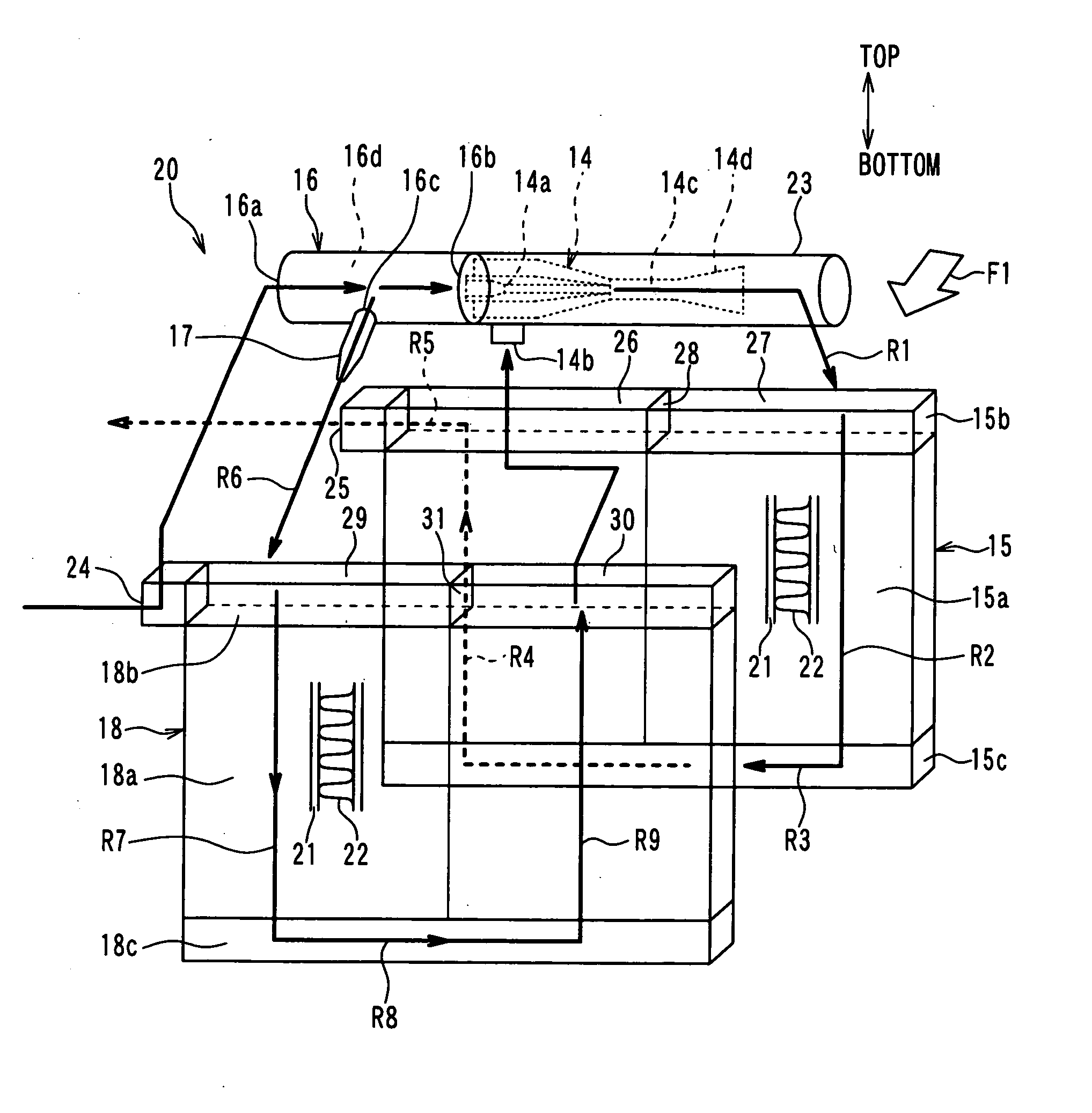
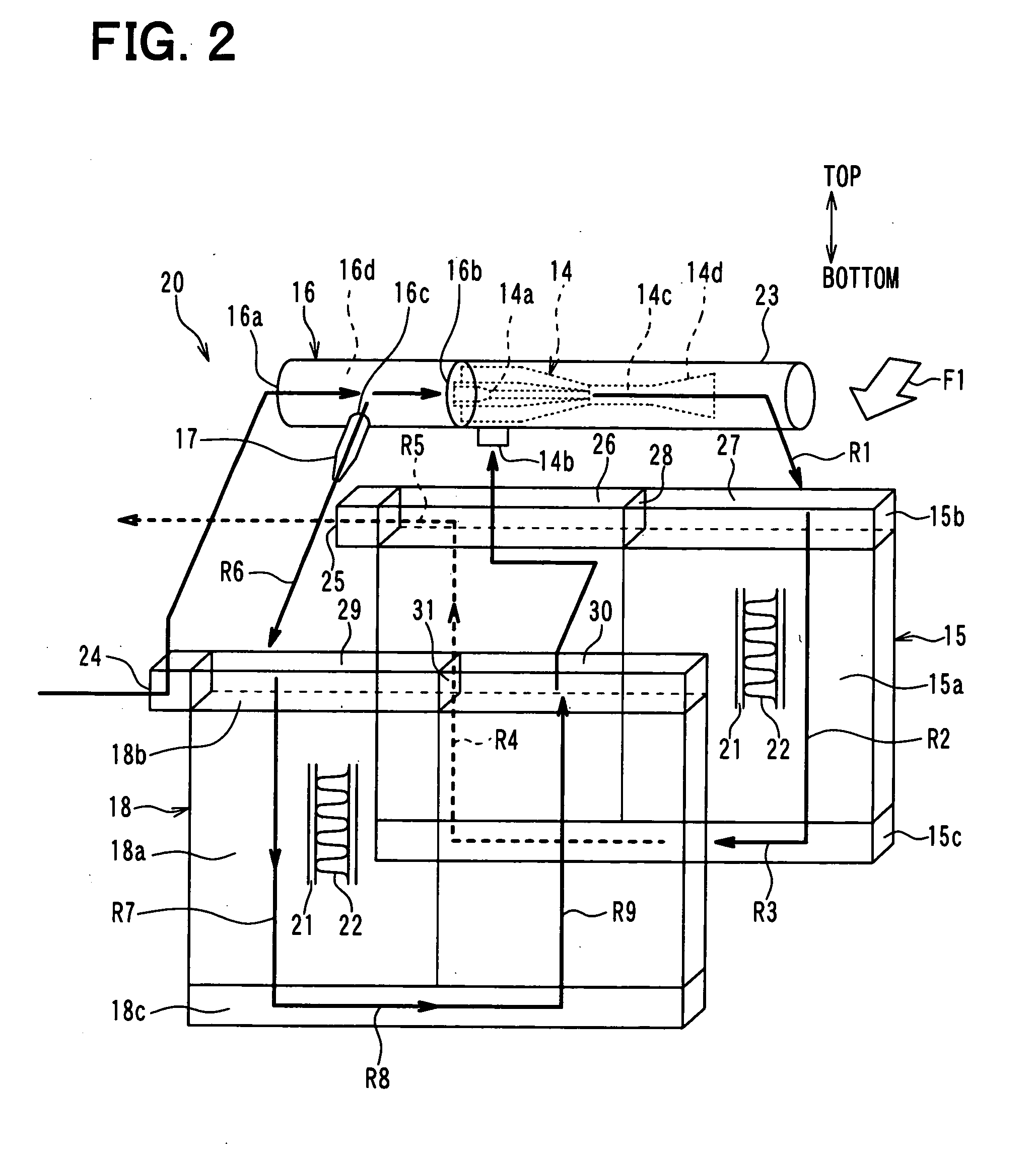
[0046]A first embodiment of the present invention will be described below with reference to FIGS. 1A to 5B. In the present embodiment, an evaporator unit of the present invention will be typically used for a refrigerant cycle device. The evaporator unit for the refrigerant cycle device is an integrated evaporator unit in which plural components of a refrigerant cycle, such as an evaporator, an ejector and a flow amount distributor, are integrally disposed.

[0047]The integrated evaporator unit is connected to other components of the refrigerant cycle, including a condenser, a compressor, and the like, via piping to constitute a refrigerant cycle device with an ejector. The integrated evaporator unit of the embodiment is used for an indoor equipment (e.g., evaporator) for cooling air. The integrated evaporator unit may be used as an outdoor equipment in other embodiments.

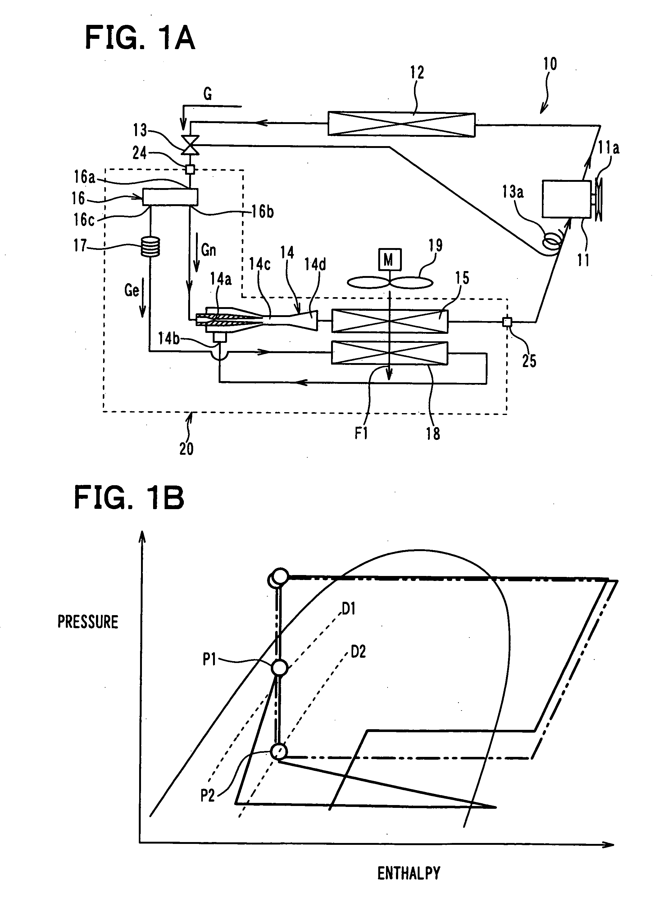
[0048]FIG. 1A shows an example of an ejector refrigerant cycle device 10 for a vehicle according to the first embodi...

second embodiment

[0137]A second embodiment of the present invention will be described with reference to FIGS. 6A and 6B. In the above-described first embodiment, the single throttle mechanism 17 is attached to the flow amount distributor 16 at a position of the cylindrical wall surface of the flow amount distributor 16. That is, the second outlet port 16c is located at one position in the cylindrical wall surface of the flow amount distributor 16. However, in the second embodiment, a plurality of the throttle mechanisms 17 are attached to the cylindrical wall surface of the flow amount distributor 16, as shown in FIGS. 6A and 6B.

[0138]As shown in FIGS. 6A and 6B, the plural throttle mechanisms 17 are arranged in the axial direction (e.g., the left-right direction in FIG. 6A) of the cylindrical wall surface of the flow amount distributor 16. Specifically, the plural throttle mechanisms 17 are arranged in the arrangement direction of the plural tubes 21, to correspond to the positions of the plural tu...

third embodiment

[0141]A third embodiment of the present invention will be described with reference to FIGS. 7A and 7B. In the above-described second embodiment, the flow amount distributor 16 is formed into a simple cylindrical shape substantially having a constant outer diameter. However, in the third embodiment, as shown in FIGS. 7A and 7B, a helical groove portion 16e is formed in the inner cylindrical wall surface of the flow amount distributor 16 to be recessed from the inner cylindrical wall surface to radially outside in a helical shape, as shown in FIG. 7A. Therefore, a helical protrusion portion is formed on the outer cylindrical wall surface at the position corresponding to the helical groove portion 16e.

[0142]A plurality of the second outlet ports 16c are provided in the helical groove portion 16e of the flow amount distributor 16, and a throttle mechanism 17 is configured by the plural second outlet ports 16c by adjusting its number and its open areas. The plural second outlet ports 16...


PUM


Abstract

In an evaporator unit, a first evaporator is coupled to an ejector to evaporate refrigerant flowing out of the ejector, a second evaporator is coupled to a refrigerant suction port of the ejector to evaporate the refrigerant to be drawn into the refrigerant suction port, a flow amount distributor is located to adjust a flow amount of the refrigerant distributed to the nozzle portion and a flow amount of the refrigerant distributed to the second evaporator, and a throttle mechanism is provided between the flow amount distributor and the second evaporator to decompress the refrigerant flowing into the second evaporator. The flow amount distributor is adapted as a gas-liquid separation portion and as a refrigerant distribution portion for distributing separated refrigerant into the nozzle portion and the second evaporator. Furthermore, the flow amount distributor and the ejector are arranged in line in a longitudinal direction of the ejector.

Description

CROSS REFERENCE TO RELATED APPLICATION[0001]This application is based on Japanese Patent Applications No. 2009-004148 filed on Jan. 12, 2009, and No. 2009-268351 filed on Nov. 26, 2009, the contents of which are incorporated herein by reference in its entirety.FIELD OF THE INVENTION[0002]The present invention relates to an evaporator unit, which can be suitably used for an ejector refrigerant cycle device, for example.BACKGROUND OF THE INVENTION[0003]An ejector refrigerant cycle device is, known in JP 2007-46806A (corresponding to U.S. Pat. No. 7,513,128B2), for example. In the refrigerant cycle device, a branch portion for branching refrigerant flowing out of a refrigerant radiator is located upstream of an ejector, such that the refrigerant of one stream branched at the branch portion flows into a nozzle portion of the ejector and the refrigerant of the other stream branched at the branch portion flows into a refrigerant suction port of the ejector. The ejector is adapted to decom...

Claims


Application Information

Patent Timeline
Patent Type & Authority Applications(United States)
IPC IPC(8): F25B43/00F25B41/06
CPCF25B5/00F25B41/00F25B2500/18F25B2341/0013F25B2500/01F25B2341/0011
Inventor YAMADA, ETSUHISANISHIJIMA, HARUYUKINAKAMURA, TOMOHIKOOGATA, GOUTAOSHITANI, HIROSHIAWA, RYOKONISHINO, TATSUHIKOGOCHO, MIKA
Owner DENSO CORP
Why Eureka
Try Eureka