Test section for wind-tunnel testing apparatus and wind tunnel test apparatus employing the same

a testing section and testing apparatus technology, applied in vehicle testing, structural/machine measurement, instruments, etc., can solve the problem of not being able to measure the actual aerodynamic force acting on the vehicl

Inactive Publication Date: 2010-07-15
MITSUBISHI HEAVY IND LTD
View PDF5 Cites 23 Cited by
  • Summary
  • Abstract
  • Description
  • Claims
  • Application Information

AI Technical Summary

Benefits of technology

[0033]With the present invention, because the upstream-side suction portion, which is disposed on the floor surface located on the upstream side of the mounting section with respect to the airflow direction so as to extend in the intersecting direction that intersects the airflow direction and that sucks in the portion of the airflow near the floor surface, and the lateral suction portions, which are disposed at both sides of the mounting section and that suck in the incoming airflows flowing into the mounting section from the sides thereof, are provided, it is possible to provide the test subject with a substantially uniform airflow and to measure aerodynamic forces closer to those that actually act on the test object.

Problems solved by technology

In addition, a low velocity boundary layer forms near a floor surface due to the frictional resistance between the airflow and the floor surface, and airflows enter from the sides of the vehicle; however, these are not taken into consideration.
Therefore, with the disclosures in Patent Document 1 and Patent Document 2, it is not possible to measure the actual aerodynamic forces acting on the vehicle.

Method used


Image

  • Test section for wind-tunnel testing apparatus and wind tunnel test apparatus employing the same
  • Test section for wind-tunnel testing apparatus and wind tunnel test apparatus employing the same
  • Test section for wind-tunnel testing apparatus and wind tunnel test apparatus employing the same

Examples


Embodiment Construction

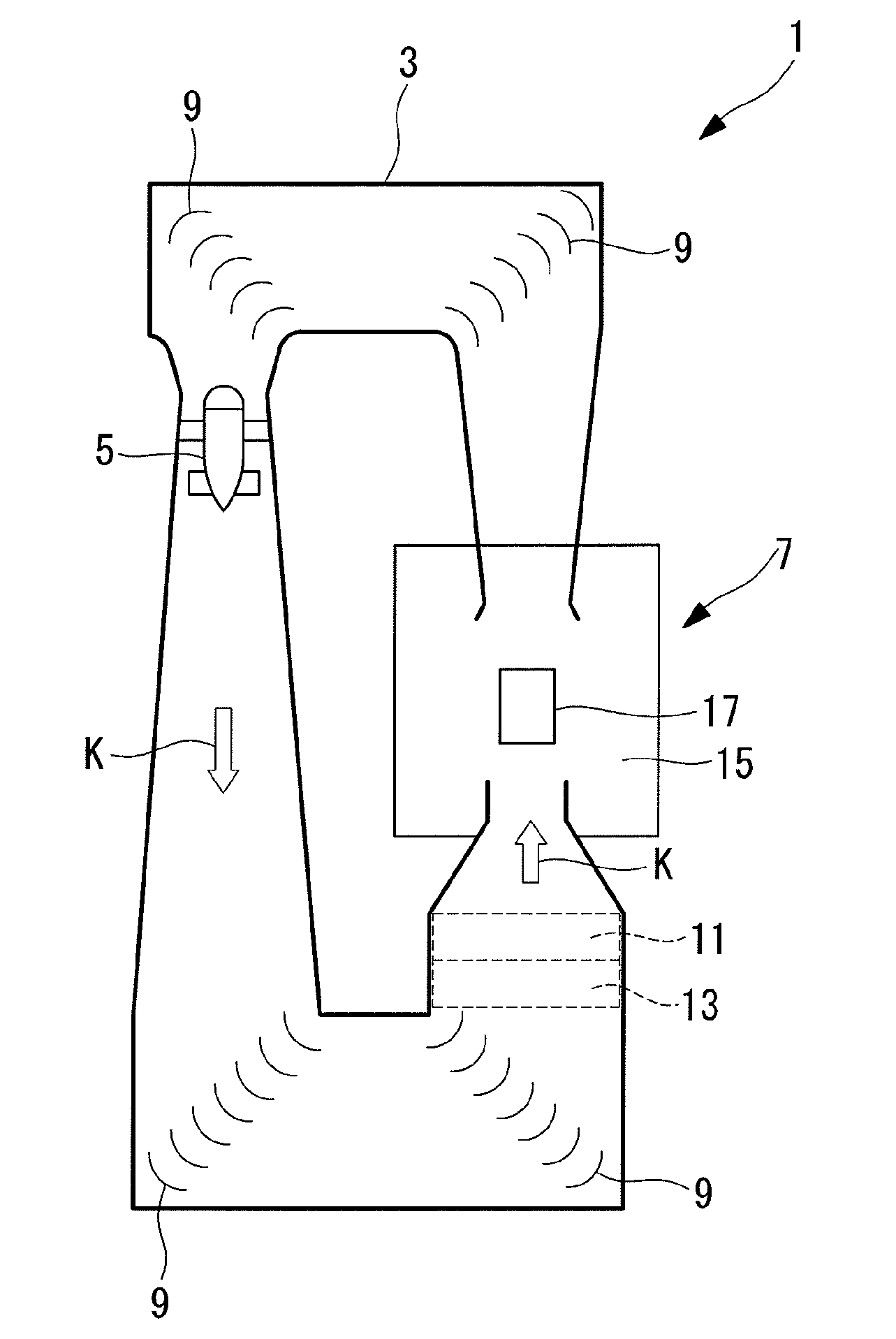
[0057]A wind-tunnel testing apparatus 1 according an embodiment of the present invention will be described below, referring to FIGS. 1 to 6. This wind-tunnel testing apparatus 1 will be described in terms of one used for measuring the aerodynamic force on an automobile.

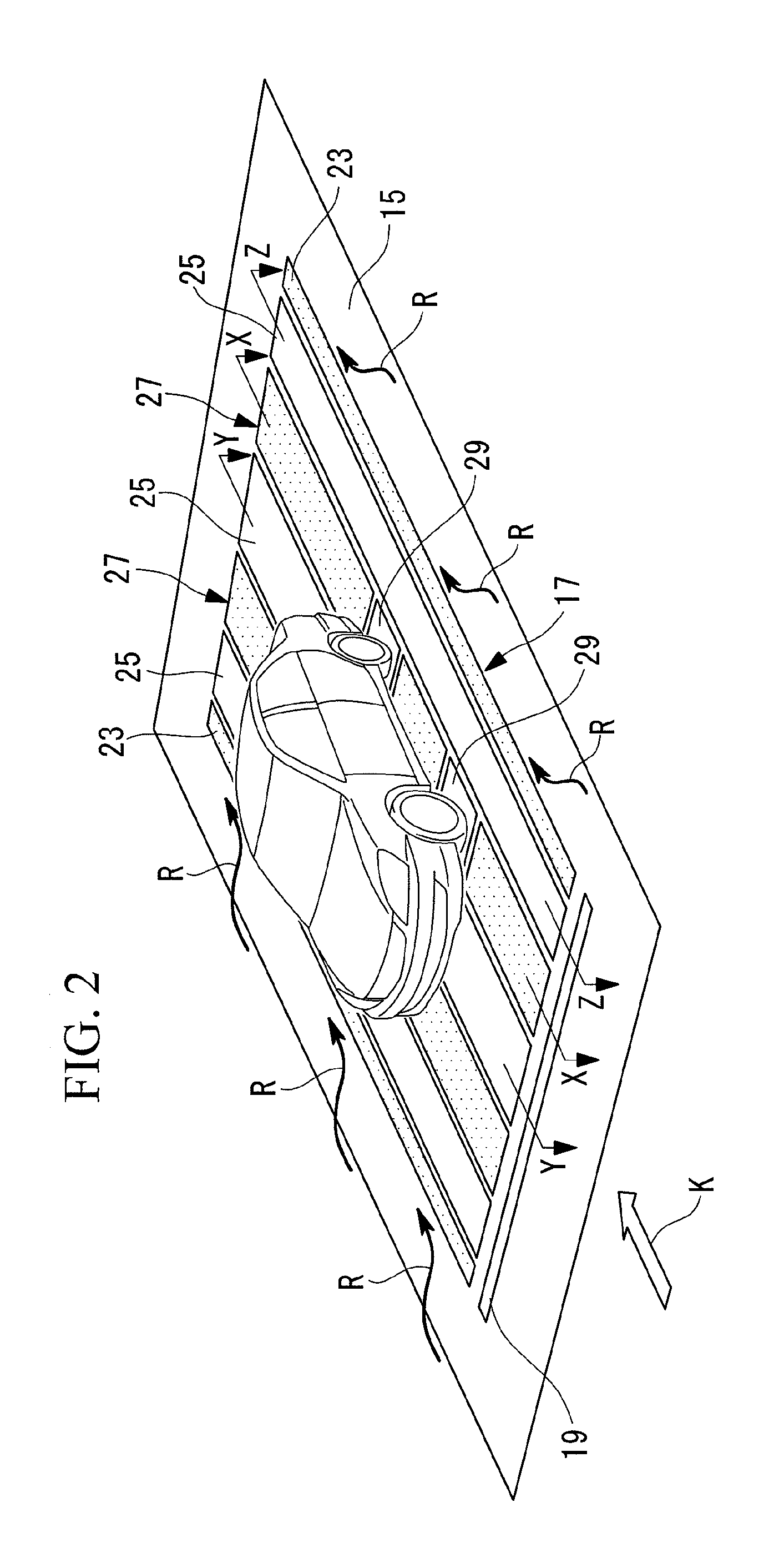
[0058]FIG. 1 is a schematic view showing, in outline, the configuration of the wind-tunnel testing apparatus 1 according to this embodiment. FIG. 2 is a perspective view showing a mounting section 17 according to this embodiment. FIG. 3 is a sectional view of FIG. 2 taken along X-X. FIG. 4 is a sectional view of FIG. 2 taken along Y-Y. FIG. 5 is a sectional view of FIG. 2 taken along Z-Z. FIG. 6 is a partial plan view showing a top plate according to this embodiment.

[0059]The wind-tunnel testing apparatus 1 is provided with a wind tunnel 3, a blower 5, and a test chamber (test section) 7.

[0060]The wind tunnel 3 is an endless structure formed in a substantially rectangular form in plan view. Corner portions of the wind...


PUM


Abstract

Provided is a test section for a wind-tunnel testing apparatus that is capable of suppressing the influences of a boundary layer on the floor surface and incoming airflows from the sides, and that is capable of measuring aerodynamic forces closer to the those actually occurring. A test section for a wind-tunnel testing apparatus having a mounting section that mounts an automobile along the internal floor surface of a wind tunnel, tests being conducted by applying an airflow blown in the wind tunnel to the automobile mounted on the mounting section, includes a slit that is disposed on the floor surface located on the upstream side of the mounting section with respect to the airflow direction so as to extend in the intersecting direction intersecting the airflow direction and that sucks in a portion of the airflow near the floor surface; and lateral suction portions, disposed at both sides of the mounting section, that suck in the incoming airflows R flowing in from the sides of the mounting section.

Description

TECHNICAL FIELD [0001]The present invention relates to a testing section for a wind-tunnel testing apparatus and to a wind-tunnel testing apparatus employing the same.BACKGROUND ART [0002]A wind-tunnel testing apparatus is generally used when evaluating aerodynamic forces on automobiles or airplanes. In particular, when evaluating aerodynamic forces including effects of the ground surface, as in vehicles such as automobiles, etc., a wind tunnel test is carried out by mounting a vehicle on a moving belt that serves as the ground surface for simulated traveling and by driving the moving belt in accordance with the airflow velocity, that is, the traveling velocity of the vehicle (see Patent Documents 1 to 3).[0003]Patent Document 1: Japanese Unexamined Patent Application, Publication No. Hei 6-341920.[0004]Patent Document 2: Japanese Unexamined Patent Application, Publication No. 2006-170639.[0005]Patent Document 3: Japanese Unexamined Patent Application, Publication No. Hei 5-248986.D...

Claims


Application Information

Patent Timeline
Patent Type & Authority Applications(United States)
IPC IPC(8): G01M9/02
CPCG01M17/0074G01M9/04
Inventor KATO, HIDEHIKOSONE, TOMOHIRO
Owner MITSUBISHI HEAVY IND LTD
Why Eureka
Try Eureka