Fluid spraying gun

a technology of spraying gun and flue, which is applied in the direction of cleaning process and equipment, cleaning using liquids, chemistry apparatus and processes, etc., and can solve the problem of small vibration of the brush

Active Publication Date: 2010-07-15
GA REW
View PDF8 Cites 24 Cited by
  • Summary
  • Abstract
  • Description
  • Claims
  • Application Information

AI Technical Summary

Benefits of technology

[0008]According to the present invention, when the supply path of gas from the gas supply source is opened by the open / close portion through rotation of the lever provided on the gripping portion, gas supplied from the gas supply source is separated by the flow separation portion, and one portion of gas is sprayed from the tip of the nozzle toward the brush implanted in the ring-shape front end portion of the tube-shape guide, while the nozzle undergoes the gyrating motion under the guidance of the tube-shape guide. At the same time, the other portion of gas separated by the flow separation portion is directed toward the inside of the tube-shape guide and sprayed from the inner nozzle to the inside of the liquid distribution pipe, and liquid is drawn up from the liquid supply source through the liquid distribution pipe due to the negative pressure occurring at this time. This liquid is formed into minute drops by mixing with the gas from the inner nozzle, and is sprayed on the inside of the tube-shape guide. Liquid formed into minute drops in this way and sprayed on the inside of the tube-shape guide is mixed with gas sprayed toward the brush from the tip of the nozzle which undergoes the gyrating motion, further creating minute drops which are sprayed forward from the tube-shape guide. At this time, liquid is drawn up by the liquid distribution pipe, provided separately from the nozzle, so that an adequate amount of liquid can be drawn up. Hence liquid at an adequate flow rate can be mixed with gas to form minute drops and sprayed. Moreover, at this time slight vibrations occur in the brush due to the gas from the gyrating nozzle. For this reason, merely by pressing the brush against an object to be cleaned, cleaning can be performed with the brush, which undergoes slight vibrations while spraying water formed into minute drops. Further, water which has once been absorbed by the brush is further converted into minute drops and sprayed by the high-speed vibrations (5000 to 6000 per minute) of the brush. As a result, cleaning can be performed even of detailed portions of the object to be cleaned, with which the brush does not come into direct contact.

Problems solved by technology

Moreover, at this time slight vibrations occur in the brush due to the gas from the gyrating nozzle.

Method used


Image

  • Fluid spraying gun
  • Fluid spraying gun

Examples


Embodiment Construction

[0010]A fluid spraying gun of one embodiment of the invention is explained below, referring to the drawings.

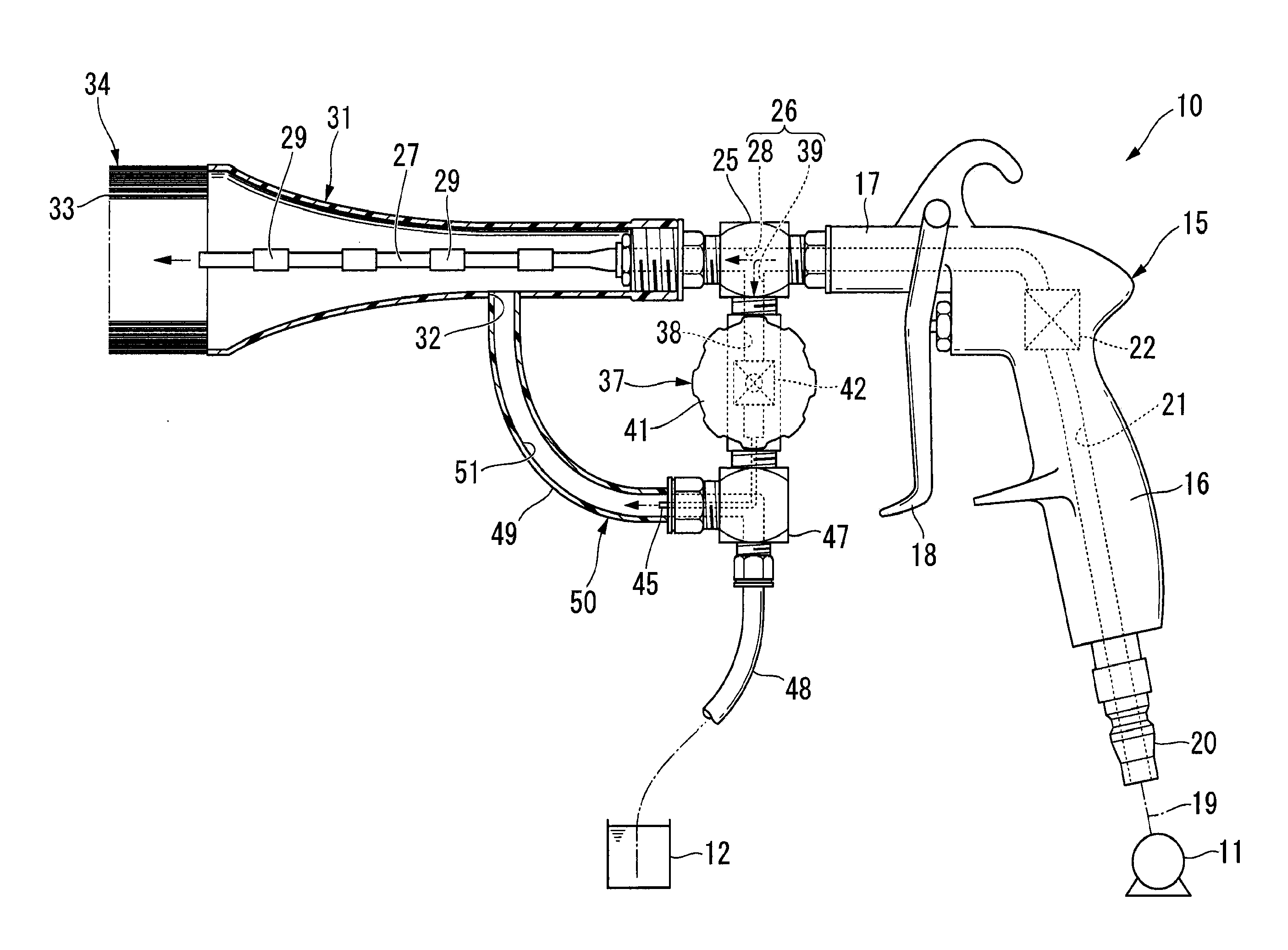
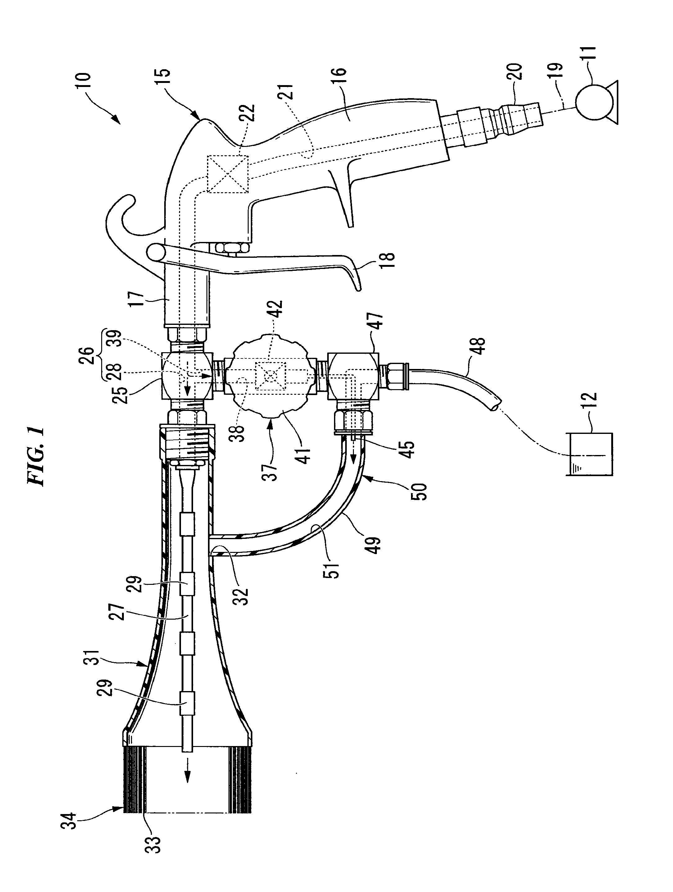
[0011]As shown in FIG. 1, a fluid spraying gun 10 of this embodiment is connected to an air compressor 11 serving as a gas supply source, and receives a supply of compressed air as the gas, and in addition receives a supply of liquid, for example, water or a liquid cleanser, stored in a tank 12 serving as a liquid supply source; the fluid spraying gun 10 mixes the gas and liquid and sprays the mixture to clean an object to be cleaned. Of course, supplies of various other gases and liquids can also be received.

[0012]The fluid spraying gun 10 of this embodiment has a gun main unit 15. This gun main unit 15 has a gripping portion 16, which is gripped by the user; a forward-extending portion 17, extending forward from one end of the gripping portion 16; a rotatable lever 18, provided on the gripping portion 16 so as to be positioned along the gripping portion 16; a joint portion 2...


PUM


Abstract

A fluid spraying gun of the present invention includes: a tube-shape guide, on which a brush extending forward is implanted; a nozzle, which is formed of a flexible pipe member with a front end thereof as a free end, and sprays one portion of gas, which is supplied from the flow separation portion and passes through the nozzle, toward the brush from the front end thereof, while the nozzle undergoes the gyrating motion guided by the tube-shape guide; an inner nozzle, which sprays gas which has passed through a flow rate adjustment portion from a tip portion thereof; and a liquid distribution pipe, which penetrates the tube-shape guide, links an inside of the tube-shape guide with a liquid supply source, has an intermediate portion into which the inner nozzle is inserted in a state where the inner nozzle is directed toward the tube-shape guide, and draws up liquid from the liquid supply source by a negative pressure arising from spraying of gas by the inner nozzle to cause spraying of liquid on the inside of the tube-shape guide. According to the present invention, it is possible to provide a fluid spraying gun in which a liquid with an adequate flow rate can be mixed with a gas, converted into minute drops and sprayed.

Description

TECHNICAL FIELD[0001]The present invention relates to a fluid spraying gun which sprays a fluid.[0002]Priority is claimed on Japanese Patent Application No. 2007-176367, filed Jul. 4, 2007, the content of which is incorporated herein by reference.BACKGROUND ART[0003]Technology relating to a fluid-spraying gun which sprays fluid includes a gun comprising a dual nozzle, having an outer nozzle and an inner nozzle both with flexibility (see for example Patent Reference 1). In this fluid-spraying gun, a gas supplied from a gas supply source passes through the gap between the outer nozzle and the inner nozzle of the dual nozzle and is sprayed. The negative pressure arising from spraying of the gas, while circulating the dual nozzle within a tube-shape guide positioned on the outside of the dual nozzle, causes the liquid in the liquid supply source to be sucked up from the inner nozzle and mixed with the gas, causing the liquid to be converted into minute drops and to be sprayed while circ...

Claims


Application Information

Patent Timeline
Patent Type & Authority Applications(United States)
IPC IPC(8): B05B7/04
CPCB05B3/00B05B7/0433B08B3/026B08B1/00B05B7/0491
Inventor HASEGAWA, KAGA
Owner GA REW
Why Eureka
Try Eureka