Radio frequency charging system

a charging system and radio frequency technology, applied in the direction of burglar alarm by hand-portable article removal, burglar alarm mechanical actuation, etc., can solve the problem of rapid consumption of the power of the rf device b>11/b>, and achieve the effect of improving transmitting/receiving efficiency and increasing charging efficiency

Active Publication Date: 2010-07-15
XUESHAN TECH INC
View PDF42 Cites 263 Cited by
  • Summary
  • Abstract
  • Description
  • Claims
  • Application Information

AI Technical Summary

Benefits of technology

[0005]In view of the foregoing issues, one object of the present invention is to provide an RF charging system and method capable of charging an RF device of a display panel and of improving charging efficiency.
[0010]One advantage of the RF charging system and method thereof according to the present invention is that, an RF device can be positioned on a display panel when the RF device is being charged. When it is determined that the RF device is not within a predetermined area, e.g., an area where an antenna has better transmitting / receiving efficiency, the predetermined area is displayed on the display panel to direct a user to relocate the RF device to the predetermined area, thereby increasing charging efficiency.

Problems solved by technology

However, when the RF device 11 communicates with the host computer 14, especially when a large amount of information is transmitted, power of the RF device 11 is consumed rapidly.

Method used


Image

  • Radio frequency charging system
  • Radio frequency charging system
  • Radio frequency charging system

Examples


Embodiment Construction

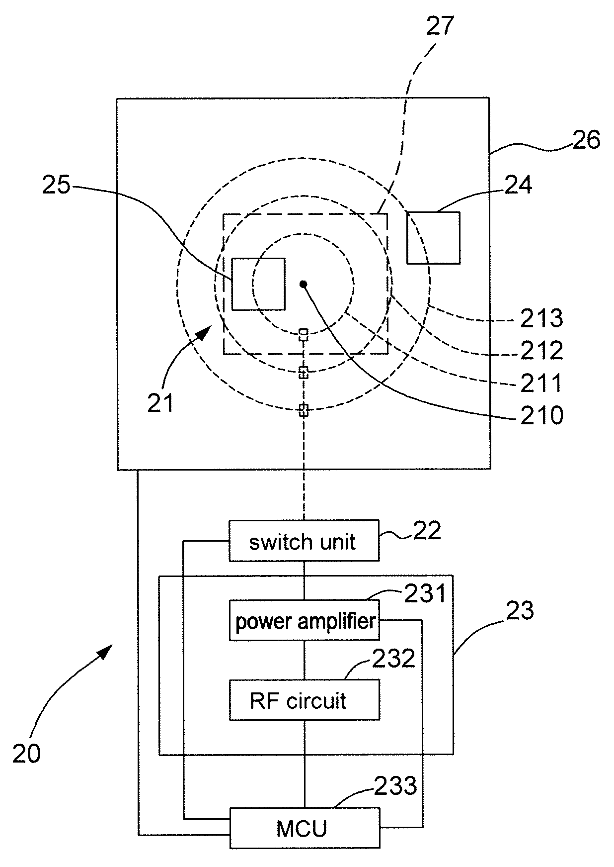
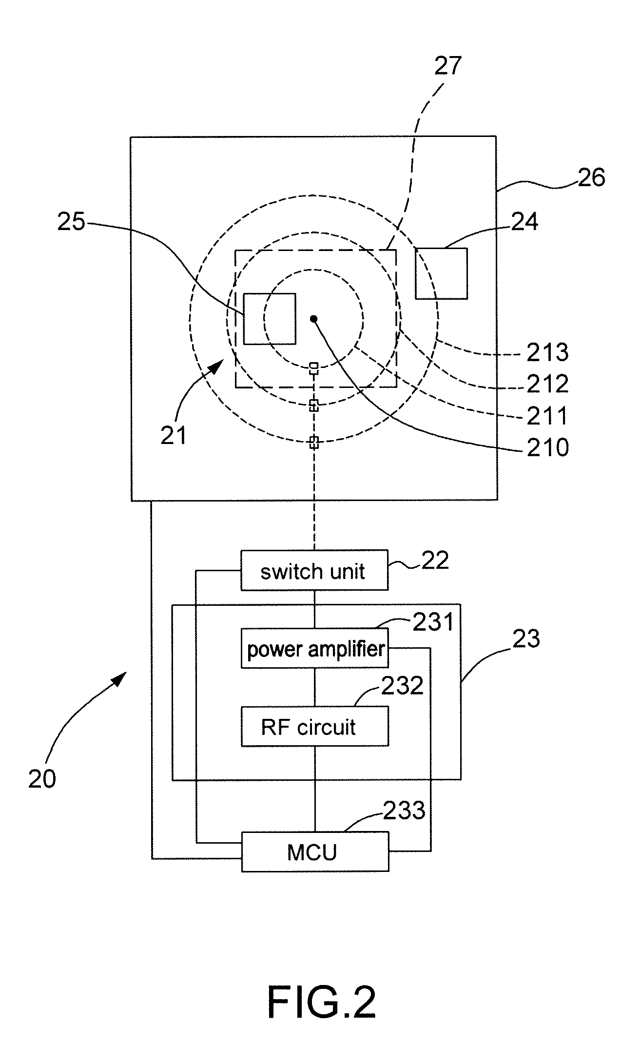
[0016]FIG. 2 is a schematic diagram of an RF charging system 20 in accordance with an embodiment of the present invention. The RF charging system 20 comprises an antenna set 21, a switch unit 22 and an RF module 23, an MCU 233 and a display panel 26. The RF charging system 20 can charge an RF device placed on the display panel 26. The RF device is an RFID tag or other portable devices having RFID functions, such as mobile phones, digital cameras, personal digital assistants (PDA), and Moving Picture Experts Group Audio Layer 3 (MP3) players. The antenna set 21 and the RF device are located at different sides of the display panel 26. For example, the RF device is on the display panel 26 and the antenna set 21 is at the back side of the display panel 26. The antenna set 21 comprises a plurality of concentric ring antennas in different sizes, such as loop antennas, and the ring antennas, being concentric, have a same center 210. Referring to FIG. 2, three ring antennas 211 to 213 are i...


PUM


Abstract

A radio frequency (RF) charging system is capable of charging an RF device on a display panel to increase charging efficiency. The RF device generates a response signal upon receiving an RF signal. The RF charging system includes an antenna set having a plurality of antennas, a switch unit, an RF module and a microcontroller unit (MCU). The MCU controls the switch unit to select one antenna from the antenna set. The antenna is able to receive the response signal and is used for transmitting the RF signal, thereby charging the RF device.

Description

CROSS REFERENCE TO RELATED PATENT APPLICATION[0001]This patent application is based on Taiwan, R.O.C. patent application No. 98101288, filed on Jan. 14, 2009.FIELD OF THE INVENTION[0002]The present invention relates to a radio frequency (RF) charging technology, and more particularly, to an RF charging system and a method capable of charging an RF device on a display panel.BACKGROUND OF THE INVENTION[0003]In recent years, as RF communication technology has progressed, various applications of near field communication (NFC) have been developed. For example, in a surface computer 10 as illustrated in FIG. 1, an RF device 11 such as a mobile phone or a radio frequency identification (RFID) tag is placed on a display panel 12. In this way, the RF device 11 can communicate with a host computer 14 through an RF module 13, which includes an antenna and an associated RF circuit and is located at the back side of the display panel 12. For example, the RF device 11 first sends pictures stored ...

Claims


Application Information

Patent Timeline
Patent Type & Authority Applications(United States)
IPC IPC(8): H04Q5/22
CPCH02J5/00H02J7/025H04B7/0802H04B5/0062H04B7/0602H02J17/00H02J50/10H02J50/402H02J50/80H02J50/90H02J50/23
Inventor CHOU, FENG-JIANHSIEH, CHIH-YUAN
Owner XUESHAN TECH INC
Why Eureka
Try Eureka