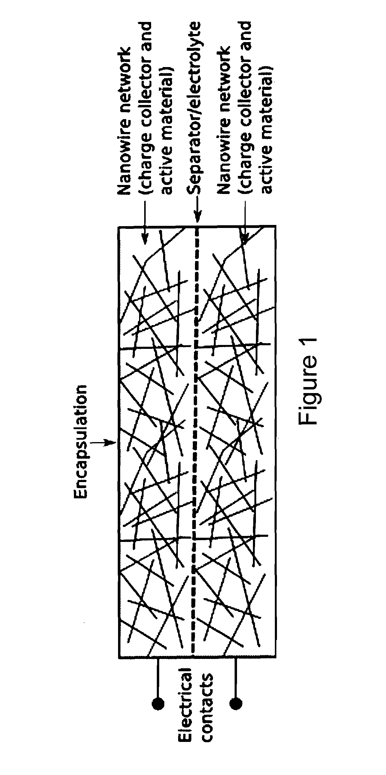
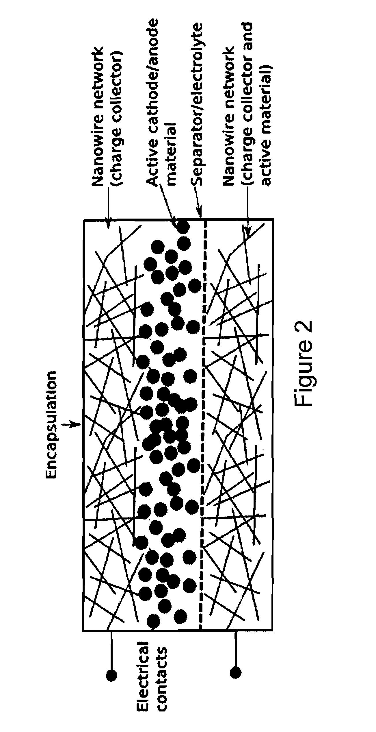
Charge storage devices containing carbon nanotube films as electrodes and charge collectors
- Summary
- Abstract
- Description
- Claims
- Application Information
AI Technical Summary
Benefits of technology
Problems solved by technology
Method used
Image
Examples
example 1
Fabrication of Supercapacitor with Free Standing Carbon Nanotube Films
[0066]1.1 Preparation of Carbon Nanotube (CNT) Suspension
[0067]1.1.1 CNT material is suspended in an aqueous or organic liquid, using a surfactant if necessary. Ultrasound is used to give a stable and homogeneous suspension in a reasonable time.
[0068]1.1.2. The CNT suspension is filtered through a membrane filter (pore size 0.1-0.01 μm) using a standard flask, a frit as filter holder and a moderate vacuum to suck through the suspension (see FIG. 17).
[0069]1.1.3 The filter cake is an entangled network of CNTs. It can be peeled off from the filter to give a freestanding CNT network which can be used as an electrode in devices according to some embodiments of this invention.
[0070]1.2 Preparation of the Capacitor
[0071]1.2.1 The freestanding CNT network is glued on a substrate and electrically contacted in this example. For the substrates, plastics have been found to work well but glass, fabrics or other material can b...
example 2
Supercapacitor with NT Electrode and Charge Collector on a Substrate
[0077]2.1 Preparation of the Capacitor
[0078]Single wall carbon nanotube (SWCNT) material was dissolved in pure water (1-2 mg / ml) with the aid of a tip sonicator. Using an air brush pistol the stable suspension was sprayed onto overhead transparencies (polyethylene-therephthalate, PET) which were placed on a heating plate at ˜100° C. During spraying, the water evaporates and the CNTs form an entangled random network on the PET. Afterwards the CNT coated PET substrates were used as thin film electrodes without any further treatment. The polymer electrolyte was prepared by mixing polyvinyl alcohol (PVA) with water (1 g PVA / 10 ml H2O) and subsequent heating under stirring to ˜90° C. until the solution becomes clear. After cooling down, concentrated phosphoric acid was added (0.8 g) and the viscose solution was stirred thoroughly. Finally, the clear solution was cast into a Petri dish where it was left to let excess wate...
example 3
Multiple Networks as Electrodes and Charge Collectors
[0127]A goal of multiple networks is to take advantage of both the high conductivity of the CNT networks and the high specific capacitance of the coating potentially increasing the capacitance of CNT networks. The second material is sprayed on top of the CNT networks. In such a multiple network the CNT network acts rather as the current collector whereas the additional coating is the active material. This is fundamentally different from composites where all materials are mixed together and potentially interrupting the current paths within the CNT network. The performance of these multiple networks will be discussed in terms of capacitance / area and internal resistance.
[0128]3.1 Test Results
[0129]3.1.1 Capacitance
[0130]In FIG. 31, the capacitance / area before and after coating with different materials is presented.
[0131]In general, we have observed two trends for our devices:
[0132](a) When using inorganic coatings, here MnO2 and TiO2...
PUM
 Abstract
Description
Claims
Application Information
 - R&D
- Intellectual Property
- Life Sciences
- Materials
- Tech Scout
- Unparalleled Data Quality
- Higher Quality Content
- 60% Fewer Hallucinations
Browse by: Latest US Patents, China's latest patents, Technical Efficacy Thesaurus, Application Domain, Technology Topic, Popular Technical Reports.
© 2025 PatSnap. All rights reserved.Legal|Privacy policy|Modern Slavery Act Transparency Statement|Sitemap|About US| Contact US: help@patsnap.com


