Piezoresistive pressure sensor device

a pressure sensor and piezoresistive technology, applied in the field of mems pressure sensors, can solve the problems of nonlinearity or pnl pressure, output nonlinearity becomes more problematic, etc., and achieve the effect of increasing the voltage output of the low-pressure mems sensor, and increasing the sensitivity of the sensor

Active Publication Date: 2016-05-26
VITESCO TECH USA LLC
View PDF1 Cites 10 Cited by
  • Summary
  • Abstract
  • Description
  • Claims
  • Application Information

AI Technical Summary

Benefits of technology

[0004]In accordance with embodiments of the invention the voltages output from a low-pressure MEMS sensor are increased by increasing the sensitivity of the sensor. Sensitivity is increased by thinning the diaphragm of the low pressure sensor device. Nonlinearity increased by thinning the diaphragm is reduced by simultaneously creating a cross stiffener on the top side of the diaphragm. An over-etch of the top side further increases sensitivity.

Problems solved by technology

A well-known problem with prior art MEMS pressure sensors, which use piezoresistive devices formed into a thin silicon diaphragm, is pressure nonlinearity or PNL.
Output nonlinearity becomes more problematic in sensors that are intended to detect low pressures, e.g., pressures below 10 kPa.
Another problem with thin silicon diaphragms is that they are fragile.
A major challenge is to create a diaphragm to lower or reduce PNL while improving pressure sensitivity without increasing the die size for a low pressure sensor.

Method used


Image

  • Piezoresistive pressure sensor device
  • Piezoresistive pressure sensor device
  • Piezoresistive pressure sensor device

Examples


Embodiment Construction

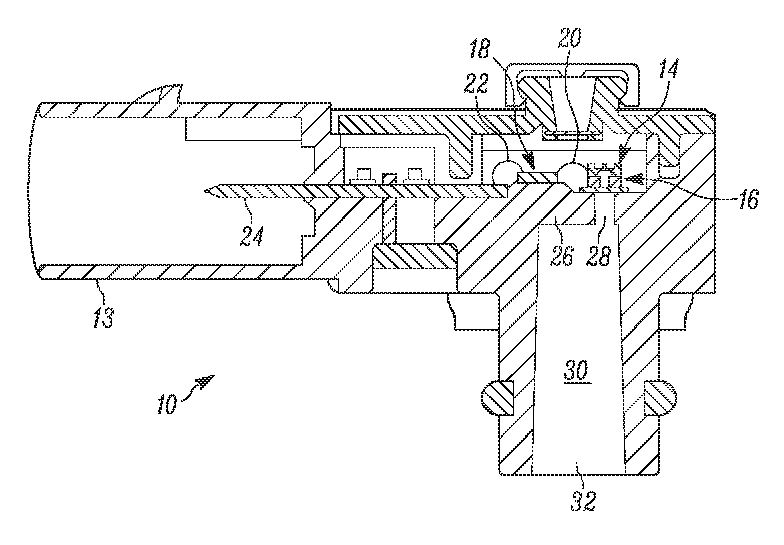
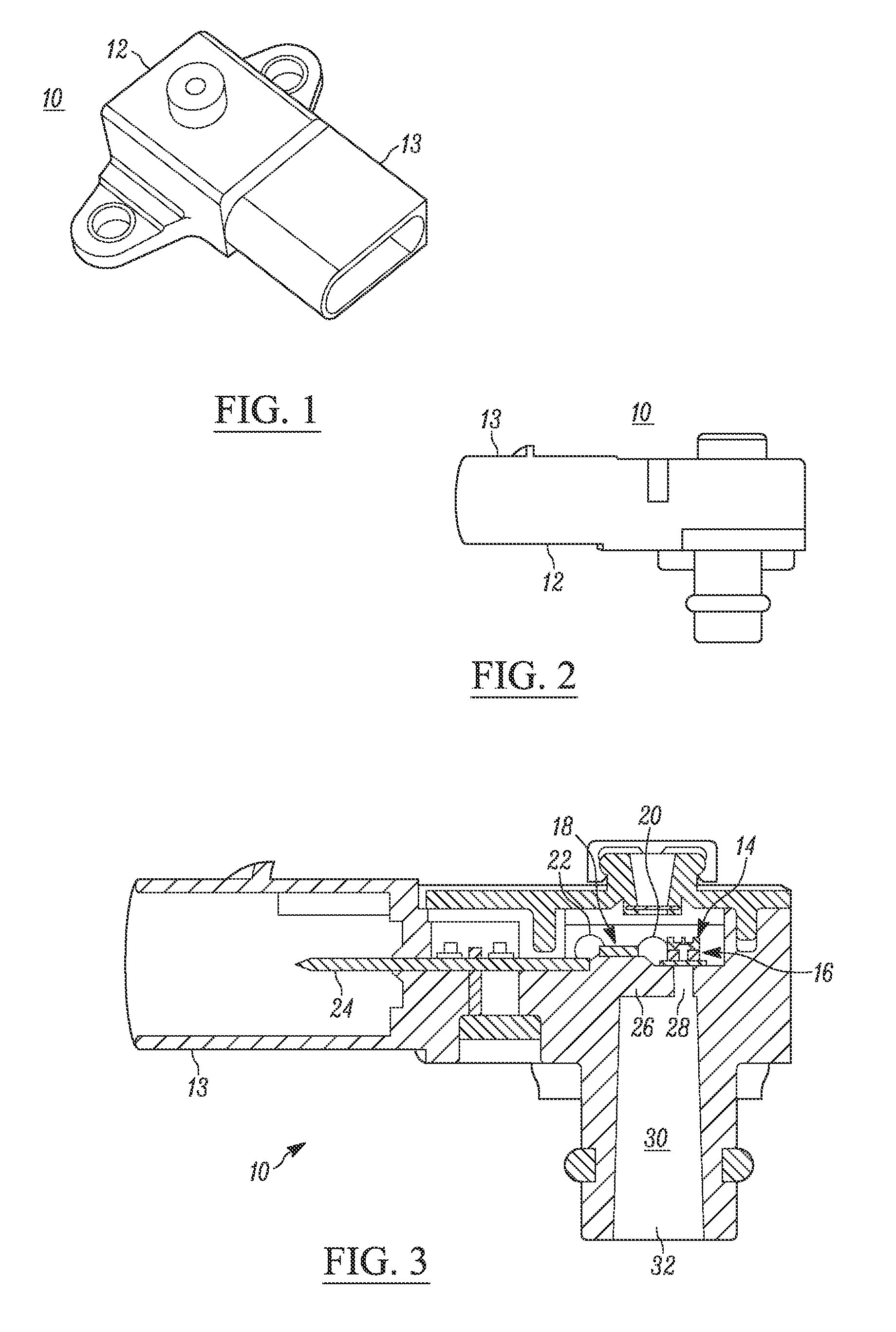
[0024]FIG. 1 is a perspective view of a pressure sensor 10 for use in automotive and industrial pressure sensing applications. FIG. 2 is a side view of the pressure sensor 10. FIG. 3 is a cross-sectional diagram of the pressure sensor 10 shown in FIG. 1 and FIG. 2.

[0025]In FIGS. 1, 2, and 3, the sensor 10 comprises an injection molded plastic housing 12 that comprises an elongated, hollow shroud portion 13. The shroud 13 protects one or more lead frame 24 that pass through the plastic material from which the housing 12 is made. The lead frame 24 provides electrical pathways into a pocket 16 inside the housing 12 where a pressure sensing element, identified by reference numeral 14, is mounted with die-mount adhesive above a hole 28 formed through a substrate 26. The hole 18 is aligned with an open passageway 30 of a port 32. A liquid or gas, the pressure of which is to be measured by the pressure sensing element 14, is able to pass through the passageway 30 and hole 18 in the substra...


PUM

PropertyMeasurementUnit
thicknessaaaaaaaaaa
thicknessaaaaaaaaaa
thicknessaaaaaaaaaa

Abstract

The voltages output from a low-pressure MEMS sensor are increased by increasing the sensitivity of the sensor. Sensitivity is increased by thinning the diaphragm of the low pressure sensor device. Nonlinearity increased by thinning the diaphragm is reduced by simultaneously creating a cross stiffener on the top side of the diaphragm. An over-etch of the top side further increases sensitivity.

Description

[0001]Solid state microelectromechanical system (MEMS) pressure sensors are well known. For example, U.S. Pat. No. 4,236,137 to Kurtz, et al. discloses a semiconductor pressure transducer. U.S. Pat. No. 5,156,052 to Johnson, et al. also discloses a solid state pressure transducer. U.S. Pat. No. 6,006,607 to Bryzek, et al. discloses a pressure sensor that uses a piezoresistive device. U.S. Pat. Nos. 5,178,016 and 6,093,579 also discloses solid state pressure sensors.BACKGROUND[0002]A well-known problem with prior art MEMS pressure sensors, which use piezoresistive devices formed into a thin silicon diaphragm, is pressure nonlinearity or PNL. The PNL is a function of the silicon diaphragm's deflection. The greater the diaphragm deflection, the greater degree of output nonlinearity, whether the piezoresistance is detected and measured as a voltage or current.[0003]Output nonlinearity becomes more problematic in sensors that are intended to detect low pressures, e.g., pressures below 10...

Claims


Application Information

Patent Timeline
Patent Type & Authority Applications(United States)
IPC IPC(8): G01L9/00B81C1/00
CPCG01L9/0052B81C2201/013B81C1/00158G01L9/0044G01L9/0045G01L9/0047G01L9/0054B81B3/007B81B2201/0264B81B2203/0127G01L9/06
Inventor CHIOU, JEN-HUANG ALBERTCHEN, SHIUH-HUI STEVEN
Owner VITESCO TECH USA LLC
Why Eureka
Try Eureka