Laser marking apparatus with diode laser matrix

a laser matrix and laser marking technology, applied in laser beam welding apparatus, digitally marking record carriers, instruments, etc., can solve the problems of difficult sitement in production lines, high cost of co.sub.2 laser tubes, and inclusion of acousto-optical deflectors

Inactive Publication Date: 2001-03-13
MACSA ID
View PDF18 Cites 22 Cited by
  • Summary
  • Abstract
  • Description
  • Claims
  • Application Information

AI Technical Summary

Benefits of technology

According to the invention, the laser beams are directed from the diodes to the focusing system by optical fibre lines, one optical fibre line, for example, being used for each diode or for each array of diodes so as to eliminate conventional beam directing optical elements and thus avoid the problems and difficulties associated therewith such as the corresponding adjustment and alignment.
In addition to the above-mentioned advantages, the system according to the invention also requires a much smaller system for refrigerating the laser diodes than that used in the CO.sub.2 laser since the energy output of the laser diodes is much higher.

Problems solved by technology

Although this type of system operates perfectly, it has the drawback that the CO.sub.2 laser tube has very large dimensions so it is difficult to site it in production lines.
A further drawback is that CO.sub.2 laser tubes are very expensive.
It should also be mentioned that this type of system has the drawback that it is necessary to include an acousto-optical deflector which, apart from its cost, does not have a very high power output owing to the losses by absorption and the low efficiency of deflection, due to the fact that it loses laser power by the mere fact of passing through the crystal of the deflector and, furthermore, a proportion of the resultant power cannot be deflected owing to the intrinsic limitations of acousto-optical deflection.

Method used


Image

  • Laser marking apparatus with diode laser matrix
  • Laser marking apparatus with diode laser matrix
  • Laser marking apparatus with diode laser matrix

Examples


Embodiment Construction

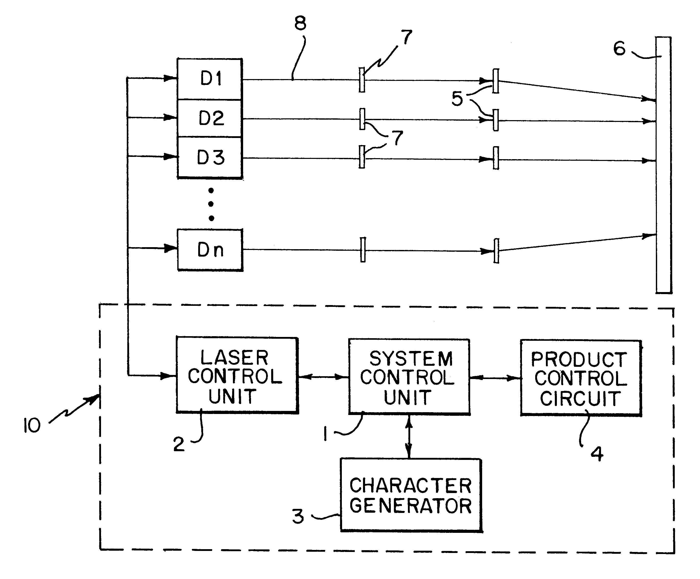
To overcome the above-mentioned drawbacks and deficiencies, the invention has developed a new laser beam marking system using a marking system comprising, like conventional systems:

means for generating a laser beam;

optical means for focusing the laser beam on the surface to be marked;

a marking control unit for generating distinct signals which are applied to the means for generating a laser beam and to the optical focusing means to produce the marking according to a N.times.M matrix of dots;

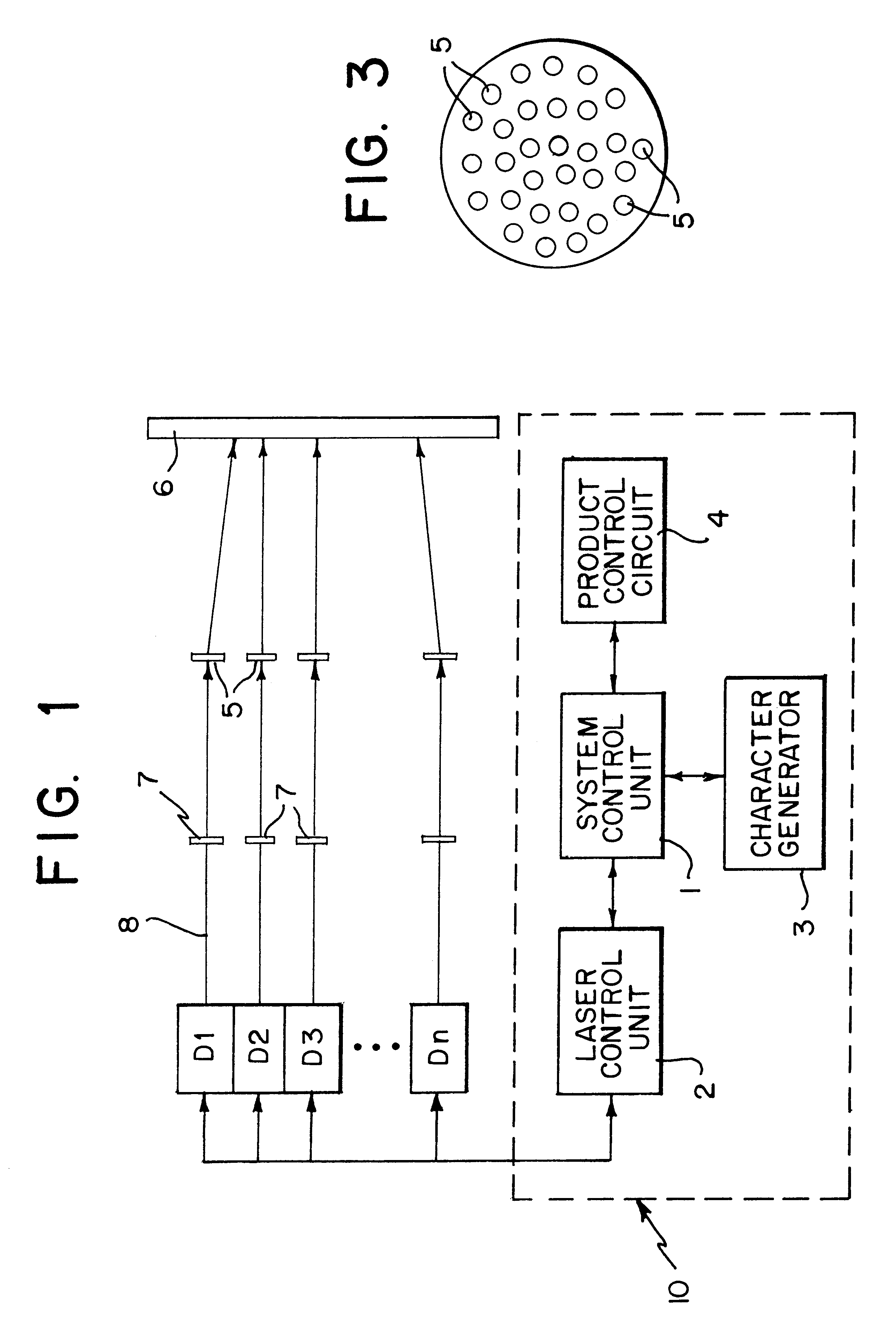
a character generator included in the actual marking control unit and with the feature that it is characterised in that the means for generating the laser beam are formed by at least one laser diode for each dot N of the matrix, N being the vertical dots or raster dots or for at least one laser diode for each of the N.times.M dots of the marking matrix, M being the number of dots of the width of the matrix.

This arrangement avoids the use of CO.sub.2 laser tubes which are very large in size and ar...


PUM

PropertyMeasurementUnit
angleaaaaaaaaaa
energyaaaaaaaaaa
volumeaaaaaaaaaa

Abstract

A laser marking system includes a means for generating a laser beam and a marking control unit which generates individual signals applied to a laser system for producing an NxM matrix of dots used to mark an object. Each dot is created from the laser light from at least one laser diode. If multiple lasers are used, their power can be combined with a concentrator to produce a single beam with a higher power and also provide for simplified control over the beam's power.

Description

The present invention relates to the technical field of systems for marking the surface of articles. More specifically, the invention concerns the sector of marking of surfaces of articles, including moving articles, using laser beams.It is the main object of the invention considerably to reduce the volume and price of the marking system.BACKGROUND TO THE INVENTIONIn the state of the art, it is known to use systems for marking moving objects, for example from Spanish patents n.sup.o 8901979 and n.sup.o 9602373 which describe a marking system using a laser which comprises a source of laser emission such as a CO.sub.2 laser of which the bean impinges on an acousto-optical deflector to which various frequency values are applied by means of a constant gain radiofrequency amplifier, to produce different angles of deflection of the laser beam impinging on the deflector, marking the character, logo, text, etc. This information to be printed is introduced into a data acquisition unit which ...

Claims


Application Information

Patent Timeline
Patent Type & Authority Patents(United States)
IPC IPC(8): G06K1/00G06K1/12
CPCG06K1/126G06K15/1261
Inventor SANS I RAVELLAT, RAMONIBANEZ BARON, JOSE MIGUELBERINGUES I ALGUE, JORDI
Owner MACSA ID
Why Eureka
Try Eureka