A floatable wave energy converter and a method for improving the efficiency of a floatable wave energy converter

A wave energy and converter technology, applied in ocean energy power generation, machines/engines, mechanical equipment, etc., can solve problems such as low efficiency and instability, and achieve the effect of high efficiency and increased energy output

Active Publication Date: 2009-10-28
MARITIME TECH LTD
View PDF3 Cites 23 Cited by
  • Summary
  • Abstract
  • Description
  • Claims
  • Application Information

AI Technical Summary

Problems solved by technology

[0005] Although this type of wave energy converter can indeed convert wave energy into mechanical rotational energy, which can be used to drive a generator for power generation, generally speaking, this type of wave energy converter has two serious disadvantages, the first , they tend to be less efficient when converting wave energy into electrical energy, specifically, they are less efficient when converting wave energy into mechanical rotational ene

Method used


Image

  • A floatable wave energy converter and a method for improving the efficiency of a floatable wave energy converter
  • A floatable wave energy converter and a method for improving the efficiency of a floatable wave energy converter
  • A floatable wave energy converter and a method for improving the efficiency of a floatable wave energy converter

Examples


Embodiment Construction

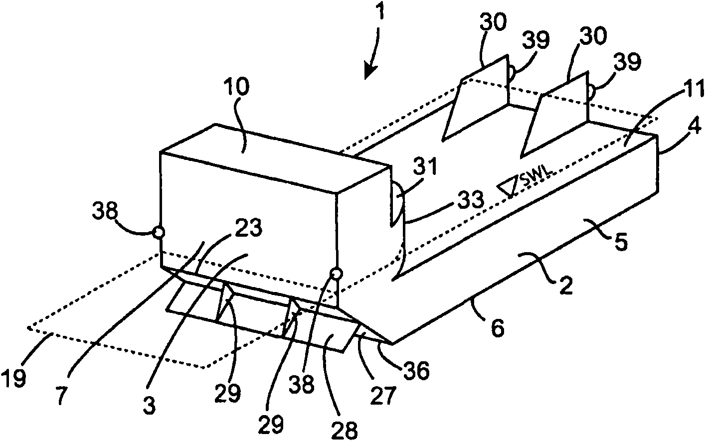
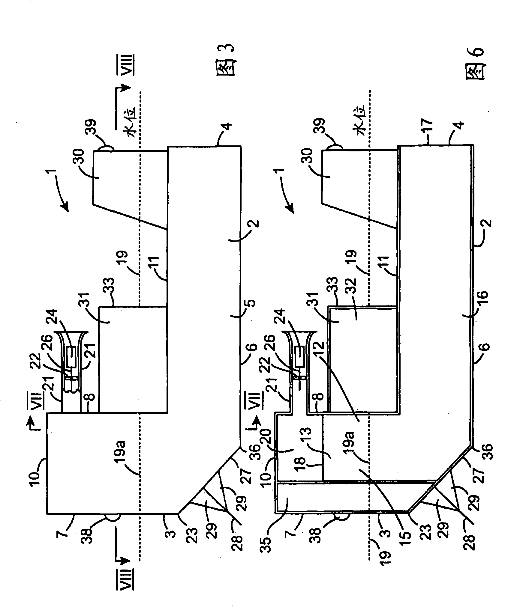
[0059] Referring to the accompanying drawings, there is shown a buoyant wave energy converter according to the present invention, denoted by reference numeral 1, for converting wave energy into mechanical rotational energy and then into electricity. The wave energy converter 1 comprises a shell 2 consisting of a structural steel frame (not shown) covered with panelling. The panels may be of any suitable material, for example sheet or plate metal, concrete or a plastic material such as fiberglass or the like. Of course, the entire shell can be constructed of reinforced concrete. The construction of such housings with structural steel frames and cover panels or other such materials is well known to those skilled in the art. The hull 2 ​​is buoyant on the ocean and extends between the front end 3 and the rear end 4, and is anchored in use with the front end 3 facing the waves so that when waves travel along the hull 2 ​​from the front end 3 to the rear end 4 When passing, it os...


PUM


Abstract

A wave energy converter (1) comprises a housing (2) extending between a forward end (3) and an aft end (4). Three upstanding air chambers (15) are located in the housing (2) and three corresponding water accommodating ducts (16) extend aft from the air chambers (15) and terminate in aft water accommodating openings (17) for accommodating water into and out of the air chambers (15) as the housing (2) oscillates by pitching in response to passing waves. An air accommodating duct (21) communicates with the air chambers (15) through a manifold (20) for accommodating air into and out of the air chambers (15) as the water level (19a) falls and rises within the air chambers (15) as the housing (2) oscillates. A self-rectifying turbine (22) located in the air accommodating duct (21) powers an electrical generator (24) for generating electricity. A buoyancy tank (31) is located on the housing (2) above the water accommodating ducts (16) aft of the air chambers (15) for maintaining the housing (2) floating in the water. A first stabilising plate (28) extending in a generally forwardly downwardly direction extends from a lower sloping portion (27) at the forward end (3) of the housing (2) for controlling the pitching oscillating motion of the housing (2) relative to wave motion for in turn enhancing the power output produced by the converter (1). A forward ballast tank (31) and a pair of second stabilising plates (30) extending upwardly from the housing (2) enhance the stability of the converter (1).

Description

technical field [0001] The present invention relates to a buoyant wave energy converter, and a method for increasing the efficiency of a buoyant wave energy converter. Background technique [0002] Wave energy converters are known for converting wave energy, eg in oceans, lakes or other expanses of water, into mechanical rotational energy. Generally speaking, mechanical rotational energy is used to drive a generator for generating electrical energy. Such wave energy converters are disclosed in European Patent Specification No. 0,950,812 to Masuda et al., US Patent Specification No. 4,741,157 to Nishikawa, and US Patent Specification No. 4,858,434 to Masuda assigned to Nishikawa. All such wave energy converters disclosed in these three prior art specifications comprise a shell extending between the front end and the rear end and anchored so that the front end faces the oncoming waves. The anchoring of the shell is arranged such that the shell oscillates due to pitching in t...

Claims


Application Information

Patent Timeline
IPC IPC(8): F03B13/24F03B13/14
CPCF03B13/24Y02E10/38Y02E10/32F05B2240/93F03B13/142Y02E10/30
Inventor M·J·M·麦卡锡M·M·惠兰
Owner MARITIME TECH LTD
Why Eureka
Try Eureka