Pole part of a medium-voltage switching device

Inactive Publication Date: 2010-07-22
ABB TECH AG
View PDF4 Cites 11 Cited by
  • Summary
  • Abstract
  • Description
  • Claims
  • Application Information

AI Technical Summary

Problems solved by technology

During operation of medium-voltage switchgear assemblies, heat is produced due to transfer resistances which limits the current carrying capacity in the region of the pole parts.
Since the pole parts of the switching device are cast into insulating material, such as an epoxy resin or plastic, the dissipation of heat which can be achieved by

Method used


Image

  • Pole part of a medium-voltage switching device
  • Pole part of a medium-voltage switching device

Examples


Embodiment Construction

[0009]Exemplary embodiments of the present disclosure provide a pole part of a switching device in which the heating of the pole part is reduced to enable production of a higher rated current carrying capacity in the pole part.

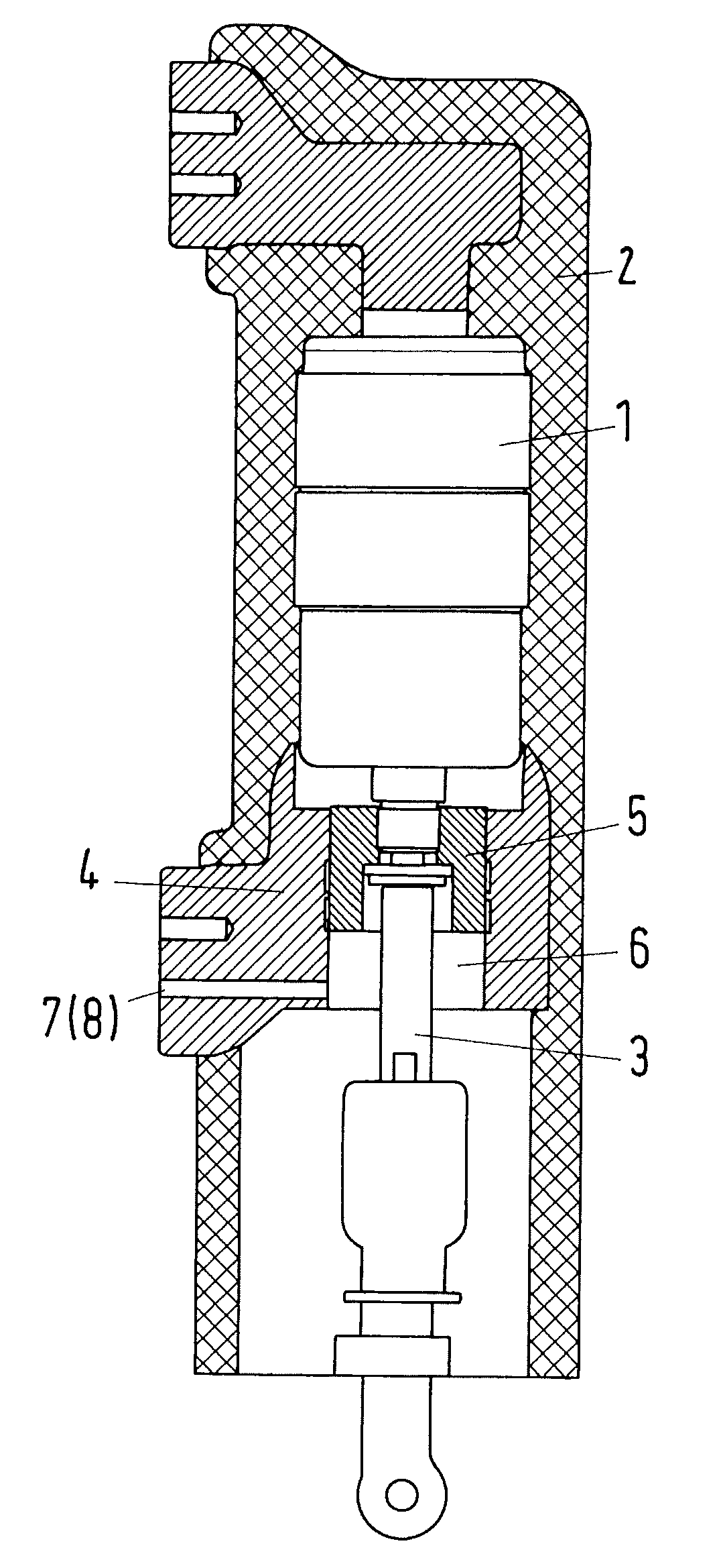
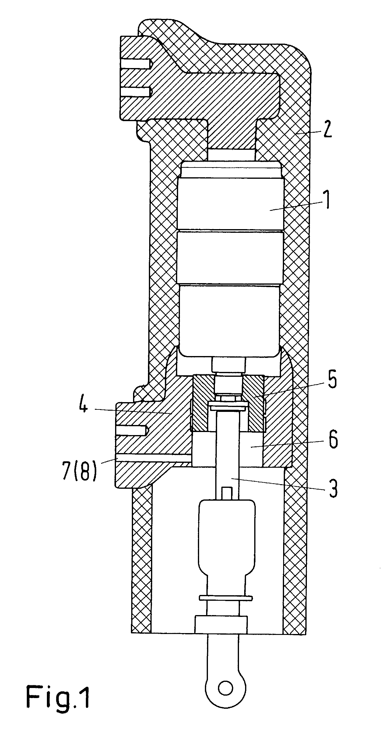
[0010]Exemplary embodiments of the present disclosure provide that, in at least one of a region of a movable contact of a vacuum interrupt chamber and an articulation point of a drive rod that drives the movable contact, at least one ventilation opening is formed to pass through at least one of an exterior wall of an insulation casing into which the vacuum interrupt chamber is cast, a boundary zone between the insulation casing and an electrical connection piece of the movable contact, and the electrical connection piece of the movable contact. Via this ventilation opening, heat dissipation by means of convection can occur directly from the pole part casing. That is to say, air or gas can now flow in through the lower opening, i.e. the opening on the base side...


PUM


Abstract

The present disclosure provides a pole part of a low-voltage, medium-voltage and/or high-voltage switching device. The pole part includes a vacuum interrupter chamber having a fixed contact and a movable contact, which includes an electrical contact piece. The vacuum interrupt chamber is cast into an insulating material. The insulating material has opening at the bottom in at least one of a region of the movable contact and a drive rod driving that drives the movable contact. To reduce the heating of the pole part to enable production of a higher rated current carrying capacity, in the region of the movable contact and/or the articulation point of the drive rod, at least one ventilation opening is formed to pass through at least one of an exterior wall of the insulation, a boundary zone between the insulation and the electrical connection piece, and the electrical connection piece.

Description

RELATED APPLICATIONS[0001]This application claims priority as a continuation application under 35 U.S.C. §120 to PCT / EP2007 / 008539 filed as an International Application on Oct. 2, 2007 designating the U.S., the entire content of which is hereby incorporated by reference in its entirety.FIELD[0002]The present disclosure relates to a pole part of a switching device having a vacuum interrupter chamber.BACKGROUND INFORMATION[0003]During operation of medium-voltage switchgear assemblies, heat is produced due to transfer resistances which limits the current carrying capacity in the region of the pole parts. Since the pole parts of the switching device are cast into insulating material, such as an epoxy resin or plastic, the dissipation of heat which can be achieved by convection is limited.[0004]The current carrying capacity is therefore limited by the maximum permissible temperature that can occur without damaging the insulating material.[0005]DE 298 25 094 U1 discloses a pole part of a ...

Claims


Application Information

Patent Timeline
IPC IPC(8): H01H33/662
CPCH01H1/5833H01H33/6606H01H2033/6623H01H2033/6613H01H33/66207
Inventor GENTSCH, DIETMAR
Owner ABB TECH AG
Why Eureka
Try Eureka