Valve apparatus for regulating a heat exchange liquid

a valve apparatus and heat exchange liquid technology, applied in the direction of machines/engines, process and machine control, instruments, etc., can solve the problems of affecting the proper operation of the wax motor actuator, the number of separate components,

Active Publication Date: 2010-07-22
DANA CANADA CORP
View PDF22 Cites 35 Cited by
  • Summary
  • Abstract
  • Description
  • Claims
  • Application Information

AI Technical Summary

Problems solved by technology

One difficulty with this known mixing valve is that it is possible for the temperature of the wax in the wax motor actuator to be influenced by not only the temperature of the liquid flowing through the first chamber but also the temperature of the coolant in the second chamber since one end of the wax motor actuator and its piston is either adjacent to or in the second chamber.
The influence of the temperature of the coolant can at least in some cases adversely affect the proper operation of the wax motor actuator.
Another difficulty with the aforementioned known mixing valve is that it requires a number of separate components or parts mounted within the valve housing for the purpose of mounting the linear actuator.
A further difficulty with the aforementioned known mixing valve is that the valve housing employs a separate end fitting which forms one end of the second chamber and which is held in the main body of the valve housing by means of a retainer clip.

Method used


Image

  • Valve apparatus for regulating a heat exchange liquid
  • Valve apparatus for regulating a heat exchange liquid
  • Valve apparatus for regulating a heat exchange liquid

Examples


Embodiment Construction

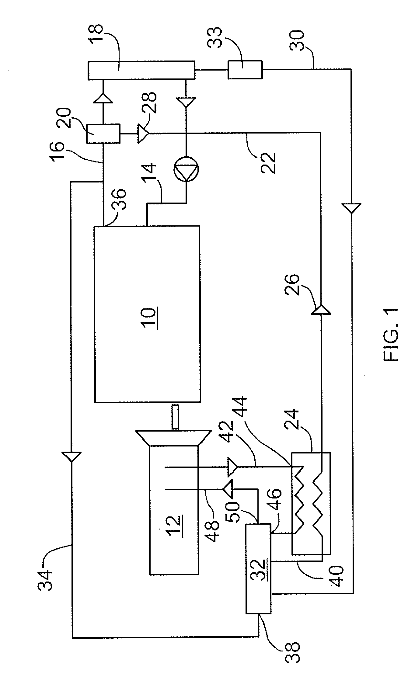
[0020]FIG. 1 illustrates schematically a cooling system for a vehicle engine 10 and a vehicle transmission 12. The engine 10 is cooled by means of passageways formed in the engine through which a coolant, normally a mixture of water and glycol can flow. This coolant, which is one form of heat exchange liquid, can flow into the engine through coolant pipe 14 and can flow out of the engine through coolant pipe 16. The coolant can be cooled by means of a standard radiator 18 having one outlet connected to the pipe 14 and an inlet connected to the pipe 16. Preferably an engine thermostat 20 is located in the line 16 and, depending on the temperature of the coolant, this thermostat is able to direct a portion of the coolant through coolant line 28 back to the engine. Connected to another outlet of the radiator 18 is a further coolant line 30 through which heat exchange liquid, i.e. coolant, at a lower temperature can flow through to the heat exchanger 24 via a valve apparatus 32 construc...


PUM


Abstract

A valve apparatus can be used to select between a cold or a hot coolant for heat exchange, this selection depending on whether an attached heat exchanger is to operate as a cooler or a heater. The apparatus includes a valve housing with first and second chambers formed therein, first inlet and outlet ports for flow of a primary liquid into and out of the first chamber and further ports for flow of coolant at different temperatures through the second chamber. A linear actuator in the housing has a body containing wax and a plastic piston that is movable to an extended position by expansion of the wax. The actuator body is located in the first chamber so the temperature of the wax is dependent on the liquid's temperature in the first chamber. An end portion of the actuator adjacent to the second chamber is made of plastic. A valve mechanism for controlling coolant flow is operably connected to the piston and located in the second chamber. This mechanism includes a spool movable by the actuator.

Description

BACKGROUND OF THE INVENTION[0001]This invention relates to valve apparatus for regulating flow of heat exchange liquid such as coolant, depending on the temperature of a second liquid, such as transmission oil.[0002]A variety of systems are known for regulating the temperature of a liquid, such as oil, using a heat exchanger or an oil cooler. In particular, it is known that one can regulate the temperature of oil used in a transmission with the objective of maintaining the temperature of the oil within a desirable temperature range so the temperature of the oil is neither too hot nor too cold. In one particular system for regulating the temperature of transmission oil by means of an oil cooler, a mixing valve is provided which is able to direct either hot coolant from a vehicle engine, for example, or cold coolant flowing from a radiator, for example, through the heat exchanger so that the heat exchanger works as a heater or as a cooler. A known form of mixing valve for regulating t...

Claims


Application Information

Patent Timeline
Patent Type & Authority Applications(United States)
IPC IPC(8): F16K15/00
CPCF01P2007/146G05D23/022F01P2060/045G05D23/1333
Inventor PALANCHON, HERVESHEPPARD, JEFFREY OWEN
Owner DANA CANADA CORP
Why Eureka
Try Eureka