
Apparatus for transceiving point to point moving signal reception high channel using hotrizontal blanking interval and method for excuting the apparatus

a technology of moving signal and apparatus, which is applied in the direction of digital transmission, television system, selective content distribution, etc., can solve the problems of unnecessary use of frequency resources, inability of video signal display apparatus and more difficult to transmit control or user data from video signal display apparatus to video signal transmission apparatus, etc., to achieve the effect of quick uplink channel

Inactive Publication Date: 2010-07-22
ELECTRONICS & TELECOMM RES INST
View PDF5 Cites 4 Cited by
  • Summary
  • Abstract
  • Description
  • Claims
  • Application Information

AI Technical Summary

Benefits of technology

The present invention provides a way to transmit video signals using a horizontal blanking interval (HBI) instead of a vertical blanking interval (VBI). This allows for the display apparatus to transmit control or user data to the transmission apparatus in an asynchronous manner. The technical effect of this invention is to secure an uplink channel and improve the efficiency of video signal transmission.

Problems solved by technology

Also, the frequency resources may be unnecessarily used.
Therefore, the video signal display apparatus cannot transmit control or user data in this interval.
Also, when considering the current tendency that the HD of the video signal transceiving apparatus is becoming more favored, it may be more difficult to transmit control or user data from the video signal display apparatus to the video signal transmission apparatus.
However, since the VBI appears only 60 times per second for 1080 p 60 f, control or user data may not be immediately transmitted as required and may need to wait until the VBI appears.

Method used


Image

  • Apparatus for transceiving point to point moving signal reception high channel using hotrizontal blanking interval and method for excuting the apparatus
  • Apparatus for transceiving point to point moving signal reception high channel using hotrizontal blanking interval and method for excuting the apparatus
  • Apparatus for transceiving point to point moving signal reception high channel using hotrizontal blanking interval and method for excuting the apparatus

Examples


Embodiment Construction

[0028]Reference will now be made in detail to embodiments of the present invention, examples of which are illustrated in the accompanying drawings, wherein like reference numerals refer to the like elements throughout. The embodiments are described below in order to explain the present invention by referring to the figures.

[0029]When it is determined detailed description related to a related known function or configuration may make the purpose of the present invention unnecessarily ambiguous in describing the present invention, the detailed description will be omitted herein.

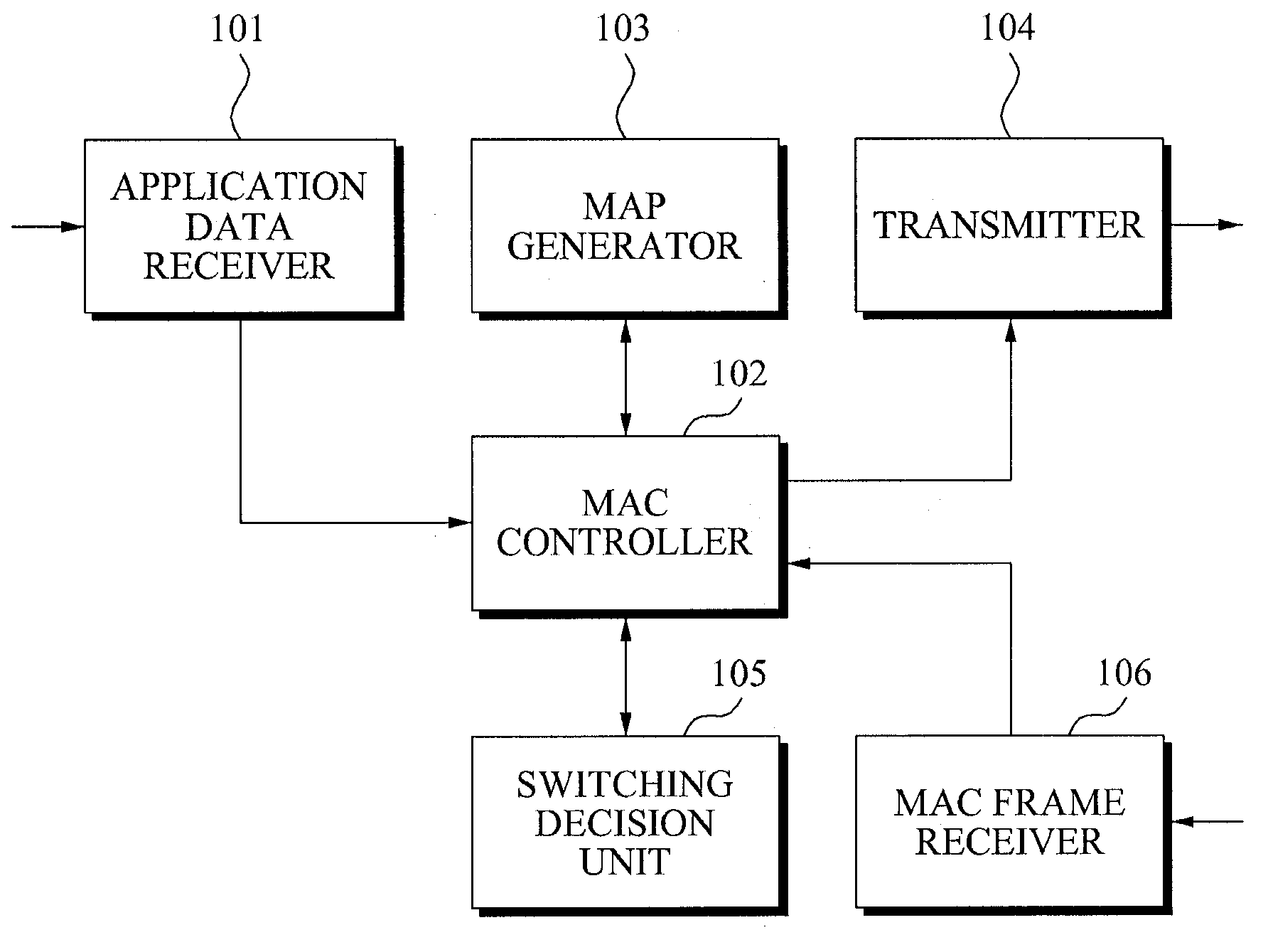
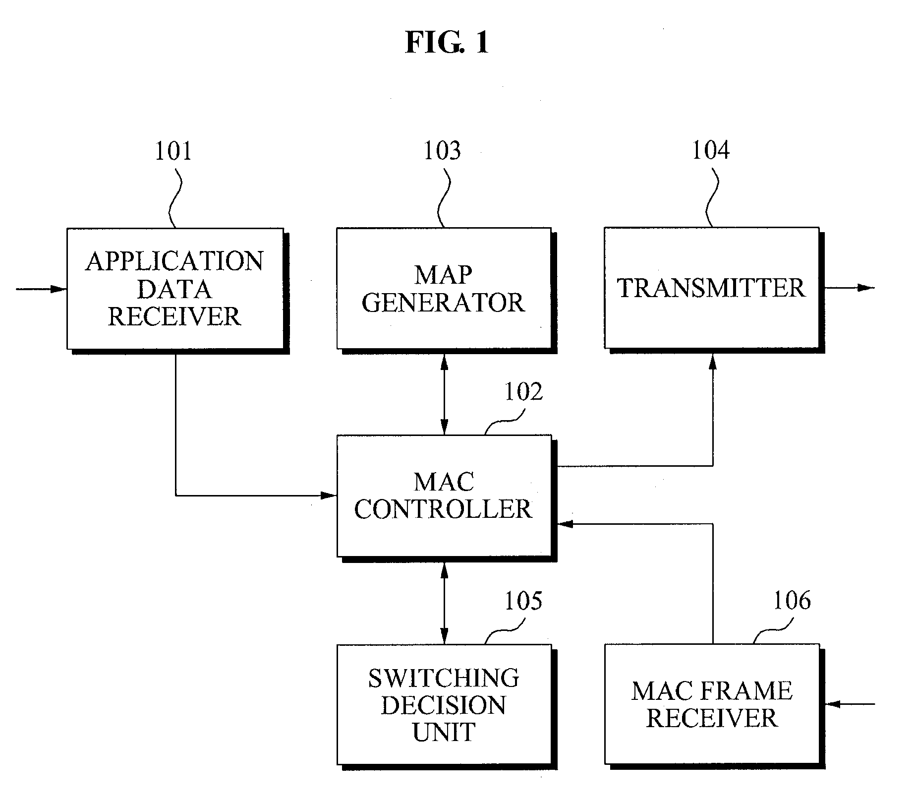
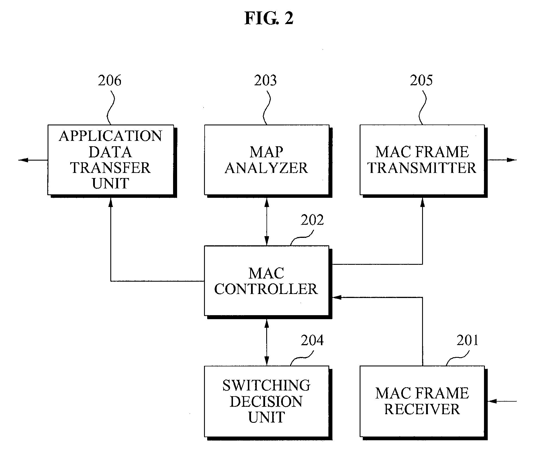
[0030]According to the present invention, there may be provided a method and apparatus for transceiving a video signal in which a video signal display apparatus can transmit control or user data to a video signal transmission apparatus. Hereinafter, the video signal transceiving apparatus will be described with reference to FIGS. 1 and 2.

[0031]FIG. 1 is a block diagram illustrating a configuration of a video sig...


PUM


Abstract

Provided are a method and apparatus for transceiving an asymmetric point-to-point moving signal and securing an uplink channel using a horizontal blanking interval (HBI) in which a video signal transceiving apparatus can combine a plurality of HBIs and a plurality of active lines (ALs) into a single section, and when auxiliary data exists in a corresponding HBI, can change an order of the HBI to the last and transmit map information including arrangement information to a video signal display apparatus, and the video signal display apparatus can receive the map information and analyze the received map information to thereby acquire an uplink channel using HBI excluding auxiliary data and transmit control signal data via the acquired uplink channel.

Description

TECHNICAL FIELD[0001]The present invention relates to an apparatus for transceiving an asymmetric point-to-point moving signal, and more particularly, to a method and apparatus for transceiving a video signal in which a video signal display apparatus can transmit control or user data to a video signal transmission apparatus via a horizontal blanking interval (HBI).[0002]This work was supported by the IT R&D program of MIC / IITA. [2007-5-002-01, Development of Multi-Gigabit Air Interface Technology]BACKGROUND ART[0003]Generally, an apparatus for transceiving a video signal denotes a data transmission system in an asymmetric point-to-point application. The data transmission system may include a video signal transmission apparatus that can transmit video and auxiliary data and a video signal display apparatus that can receive the video and auxiliary data to display the same on a screen. The video signal transmission apparatus is generally referred to as a source such as a digital video ...

Claims


Application Information

Patent Timeline
Patent Type & Authority Applications(United States)
IPC IPC(8): H04N7/084
CPCH04N7/083H04N7/085H04N21/235H04N21/435H04N7/084H04B7/24
Inventor KIM, JIN KYEONGLEE, WOO YONGKWON, HYOUNG JINKIM, KYEONGPYOKIM, YONG SUN
Owner ELECTRONICS & TELECOMM RES INST
Learn More