Eureka AIR delivers breakthrough ideas for toughest innovation challenges, trusted by R&D personnel around the world.

Assembly and Mounting Rack

Inactive Publication Date: 2010-07-22
SIEMENS AG
View PDF12 Cites 6 Cited by
  • Summary
  • Abstract
  • Description
  • Claims
  • Application Information

AI Technical Summary

Benefits of technology

[0007]It is therefore an object of the invention to provide an assembly which allows simple but secure locking and unlocking of the assembly.
[0009]In an advantageous embodiment, the second holding means has a pin which is suitable for entering a slotted-link guide. Here, the pin interacts with the slotted-link guide in the mounting rack such that the pin is guided along a rising slotted-link path by the rotary movement about the rotation point, thus resulting in an increasing pressure force of the assembly on the mounting rack.
[0012]In a further advantageous embodiment, a latching means is arranged on the center part for latching with a recess that is arranged in the housing. The latching means preferably latches in the recess in the housing in the final position of the locking lever, thus increasing a holding force on the locking lever in its final position with respect to the lower face of the assembly. The latching means prevents the locking lever from being detached, for example by vibration, from the final position from the lower face of the assembly.

Problems solved by technology

Here, the pin interacts with the slotted-link guide in the mounting rack such that the pin is guided along a rising slotted-link path by the rotary movement about the rotation point, thus resulting in an increasing pressure force of the assembly on the mounting rack.

Method used


Image

  • Assembly and Mounting Rack
  • Assembly and Mounting Rack
  • Assembly and Mounting Rack

Examples


Embodiment Construction

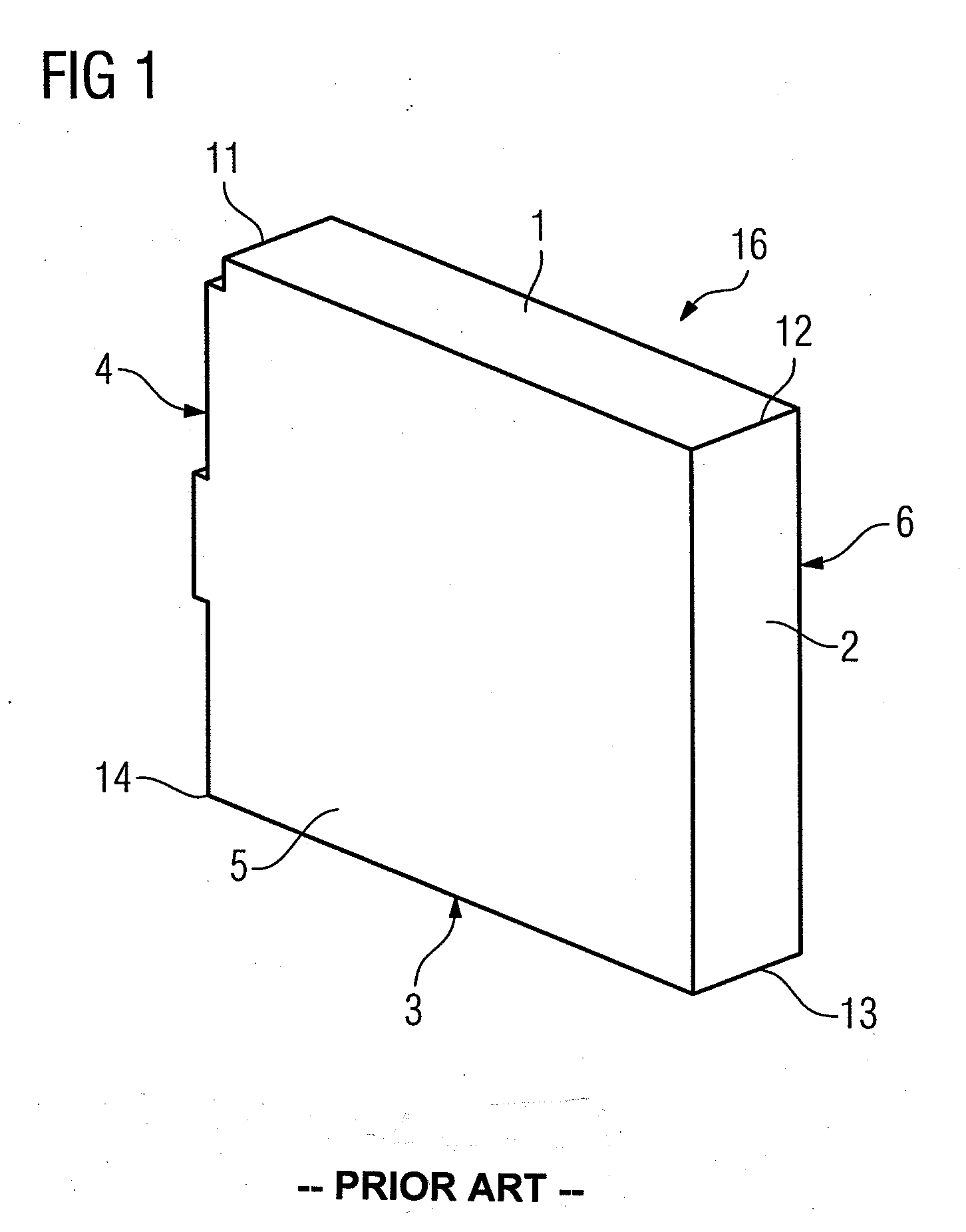
[0021]FIG. 1 shows a housing 16 in the form of a box, in accordance with the prior art and illustrates references points of the housing 16. The housing 16 comprises a rectangular box housing 16, and has a first through sixth face 1-6. Here, the fifth face 5 and the sixth face 6 represent the side surfaces of the housing 16 with the largest areas. In the corner areas of the housing 16, the housing 16 is designed with a first edge 11, a second edge 12, a third edge 13 and a fourth edge 14. The perspective illustration of the housing 16 shows it in an installed position in a mounting rack 21 (see FIG. 2). Here, the first face 1 represents an upper face of the housing 16, and the third face 3 represents a lower face of the housing 16. In a corresponding manner, the second face 2 of the housing 16 is regarded as the front face, and the fourth face 4 of the housing 16 is regarded as the rear face.

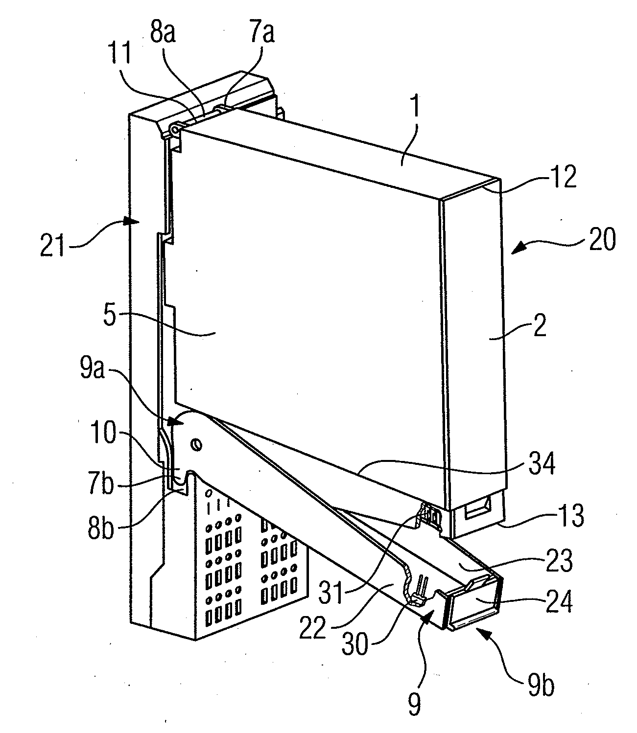
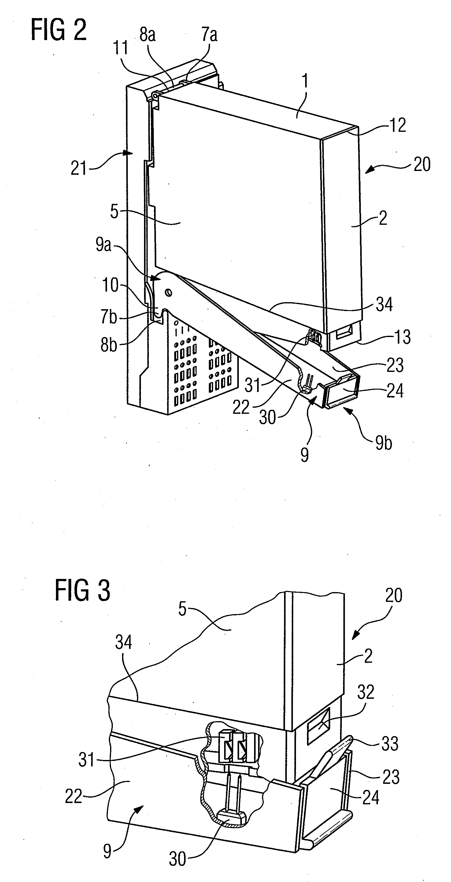
[0022]FIG. 2 shows an assembly 20 which can be pivoted into and out of a mounting rack 21. Th...


PUM


Abstract

An assembly for pivoting into a mounting rack includes a housing upon which a first holding device is arranged for connection to a first attachment device of the mounting rack. The connection permits the housing to pivot. A locking lever is rotatably mounted on the housing. A second holding device arranged at a first end of the locking lever and a second end of the locking lever is moveable in the direction of the housing for the second holding device to engage in a second attachment device of the mounting rack.

Description

BACKGROUND OF THE INVENTION[0001]1. Field of the Invention[0002]The invention relates to an assembly configured to pivot into a mounting rack, wherein the assembly comprises a housing in the form of a box on which a first holding means is arranged for connection to a first attachment means of the mounting rack, and wherein the housing can be pivoted by means of this connection. The invention also relates to a mounting rack for holding the assembly.[0003]2. Description of the Related Art[0004]In the field of automation, it is known for assemblies to be inserted into mounting racks, and for a modular system thus to be constructed. In this case, the assemblies must be securely anchored in the mounting rack, and must be secured against falling out. Furthermore, it may be important, particularly in the case of safety production or manufacturing installations, to configure an installation to allow a change of an electrical assembly during operation of the installation such that no critica...

Claims


Application Information

Patent Timeline
IPC IPC(8): F16B5/07
CPCH05K7/1409Y10T403/595
Inventor DEINHARDT, GUNTHER
Owner SIEMENS AG
Why Eureka
Eureka Blog
Learn More