Enteral Feeding Assembly With Obturator

a technology of obturator and obturator, which is applied in the direction of intravenous devices, catheters, infusion needles, etc., can solve the problems of balloon leaking and deflating, gastrostomy tubes, and difficulty in inserting retainers in body lumens

Active Publication Date: 2010-07-22
AVENT INC
View PDF3 Cites 45 Cited by
  • Summary
  • Abstract
  • Description
  • Claims
  • Application Information

AI Technical Summary

Benefits of technology

[0013]According to the present invention, the obturator and the actuator are configured to engage the distal end of the flexible catheter so that an elongating force may be applied along the longitudinal axis of the retainer to move the retainer from a deployed configuration to an insertion configuration without significantly altering the length of the flexible catheter. In an aspect of the present invention, the obturator and the actuator are configured to engage the walls of the flexible catheter defining the catheter lumen so that an elongating force may be applied along the longitudinal axis of the retainer to move the retainer from a deployed configuration to an insertion configuration without significantly altering the length of the flexible catheter.

Problems solved by technology

A problem universal to low profile and non-low profile enteral feeding devices or enteral feeding assemblies (e.g., gastrostomy tubes) is the difficulty in inserting a retainer in a body lumen to hold the enteral feeding assembly in a fixed position in the lumen.
While balloons have many advantages, balloon may eventually leak and deflate.
Other retaining fixtures have been difficult to insert through an externally stoma, and often must be endoscopically placed by a physician, usually during a surgical procedure.
This elongation of both the tube and the Malecot tip or similar expanding tip also makes withdrawal of the device more difficult because the stylet must be inserted further into the body.
This presents difficulties for smaller patients, particularly for children and babies.
The greater travel of the stylet into the body in combination with greater force applied to the stylet creates more potential for harm if the stylet is not aligned properly on the Malecot tip or similar expanding tip, if the stylet slips off the tip or if the tip fails and separates from the tube.

Method used


Image

  • Enteral Feeding Assembly With Obturator
  • Enteral Feeding Assembly With Obturator
  • Enteral Feeding Assembly With Obturator

Examples


Embodiment Construction

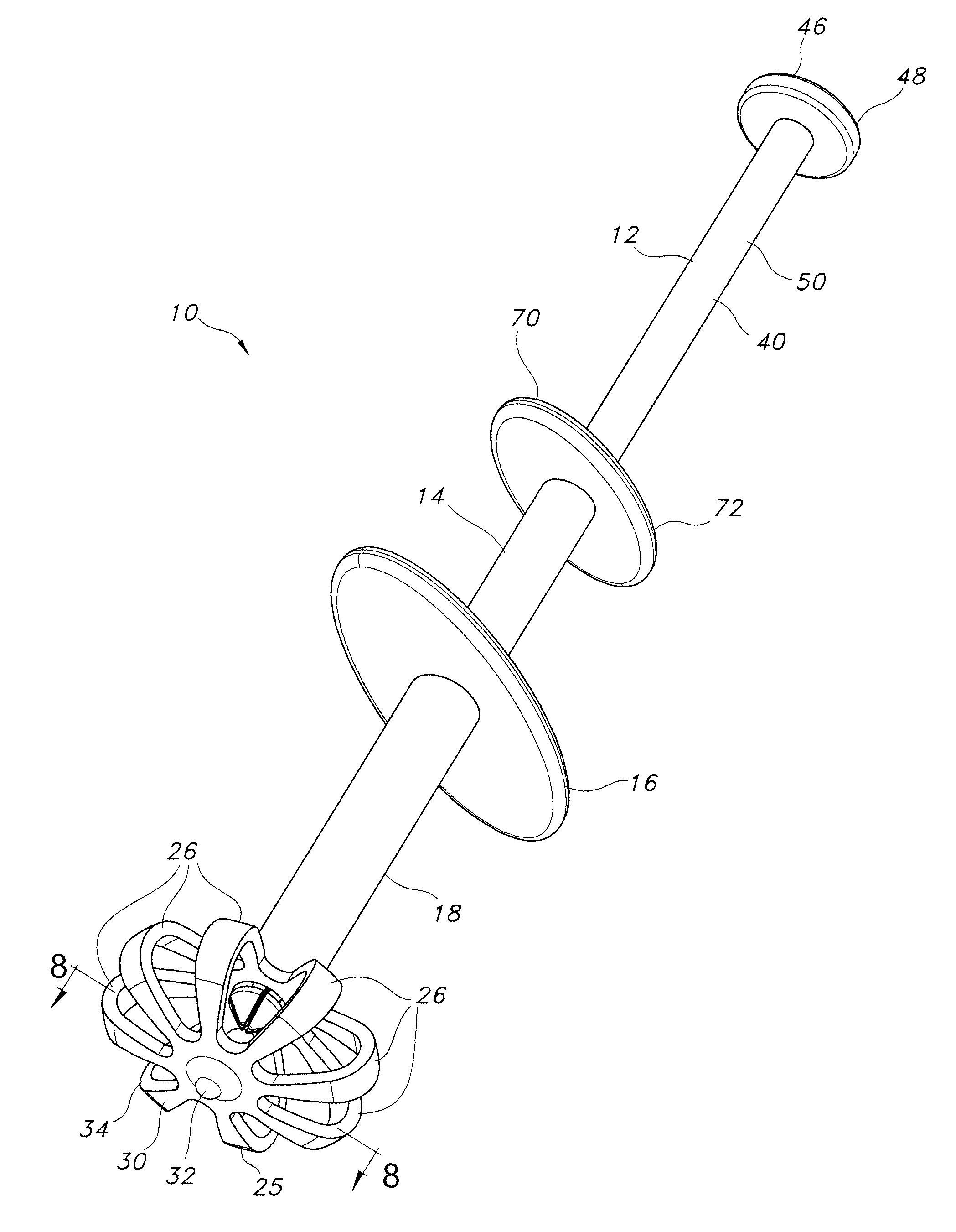
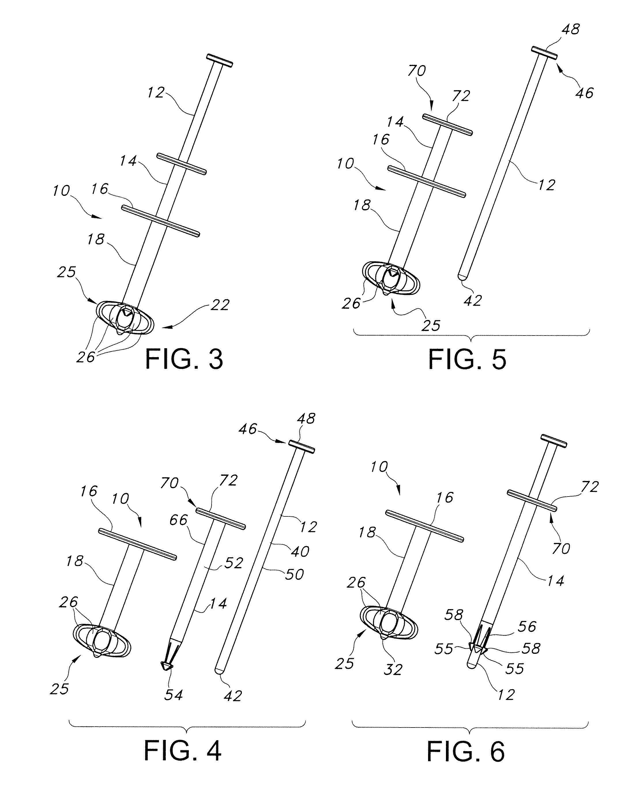
[0041]The invention(s) disclosed herein relate generally to improved medical care for patients who require enteral feeding. More particularly, the invention(s) disclosed herein relate to an enteral feeding assembly including a retainer for holding at least a portion of the assembly in a body lumen. The invention(s) disclosed herein may also include one or more devices used to insert, expand, and / or remove at least a portion of an enteral feeding assembly from a body lumen.

[0042]Reference will now be made in detail to one or more embodiments of the invention, examples of the invention, examples of which are illustrated in the drawings. Each example and embodiment is provided by way of explanation of the invention, and is not meant as a limitation of the invention. For example, features illustrated or described as part of one embodiment may be used with another embodiment to yield still a further embodiment. It is intended that the invention include these and other modifications and v...


PUM


Abstract

An enteral feeding assembly is described which includes a base and a catheter positioned through the base. A portion of the catheter extends distally away from the base, and has a retainer provided on a distal end of the catheter. The retainer includes a plurality of struts having a flexible, preformed configuration which cooperate to form at least a portion of a spherical shape with openings between the struts. A shroud is positioned over at least a proximal portion of the struts to prevent the struts from causing irritation or embedding in a body lumen. The retainer is movable between an insertion configuration and a deployed configuration. An obturator and actuator are used to move the retainer between positions. A method for inserting and removing an enteral feeding assembly is also provided.

Description

[0001]This application claims the benefit of priority from U.S. Provisional Application No. 61 / 145,727, filed on Jan. 19, 2009, the contents of which are incorporated herein by reference.FIELD OF THE INVENTION[0002]The present invention relates to improved gastrostomy tubes.BACKGROUND[0003]Numerous situations exist in which a body cavity needs to be catheterized to achieve a desired medical goal. One relatively common situation is to provide nutritional solutions or medicines directly into the stomach or intestines. A stoma is formed in the stomach or intestinal wall and a catheter is placed through the stoma. This surgical opening and / or the procedure to create the opening is common referred to as “gastrostomy”. Feeding solutions can be injected through the catheter to provide nutrients directly to the stomach or intestines (known as enteral feeding). A variety of different catheters intended for enteral feeding have been developed over the years, including some having a “low profi...

Claims


Application Information

Patent Timeline
Patent Type & Authority Applications(United States)
IPC IPC(8): A61M25/04
CPCA61J15/0015A61J15/0038A61M25/04A61J15/0065
Inventor MCMICHAEL, DONALD J.ROTELLA, JOHN A.
Owner AVENT INC
Why Eureka
Try Eureka