Medical treatment apparatus, treatment instrument and treatment method for living tissue using energy

Inactive Publication Date: 2010-07-22
OLYMPUS MEDICAL SYST CORP
View PDF7 Cites 75 Cited by
  • Summary
  • Abstract
  • Description
  • Claims
  • Application Information

AI Technical Summary

Problems solved by technology

However, since the surface of an organ is covered with components other than collagen such as epithelial cells, collagens in t

Method used


Image

  • Medical treatment apparatus, treatment instrument and treatment method for living tissue using energy
  • Medical treatment apparatus, treatment instrument and treatment method for living tissue using energy
  • Medical treatment apparatus, treatment instrument and treatment method for living tissue using energy

Examples


first embodiment

[0056]A first embodiment is described with FIG. 1A to FIG. 10B.

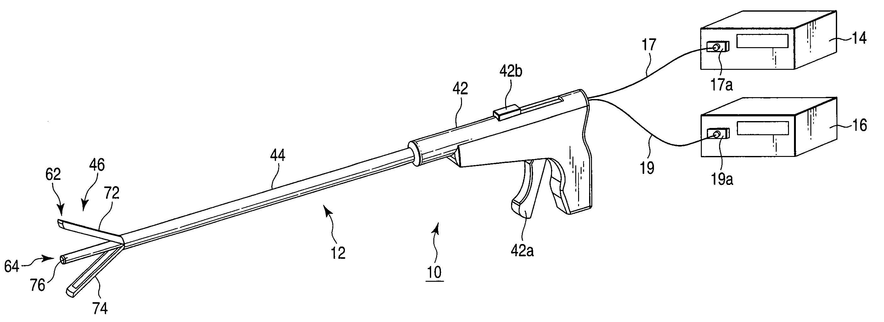
[0057]Here, a linear bipolar high-frequency energy treatment instrument 12 for a treatment, for example, through an abdominal wall is described as an example of an energy treatment instrument.

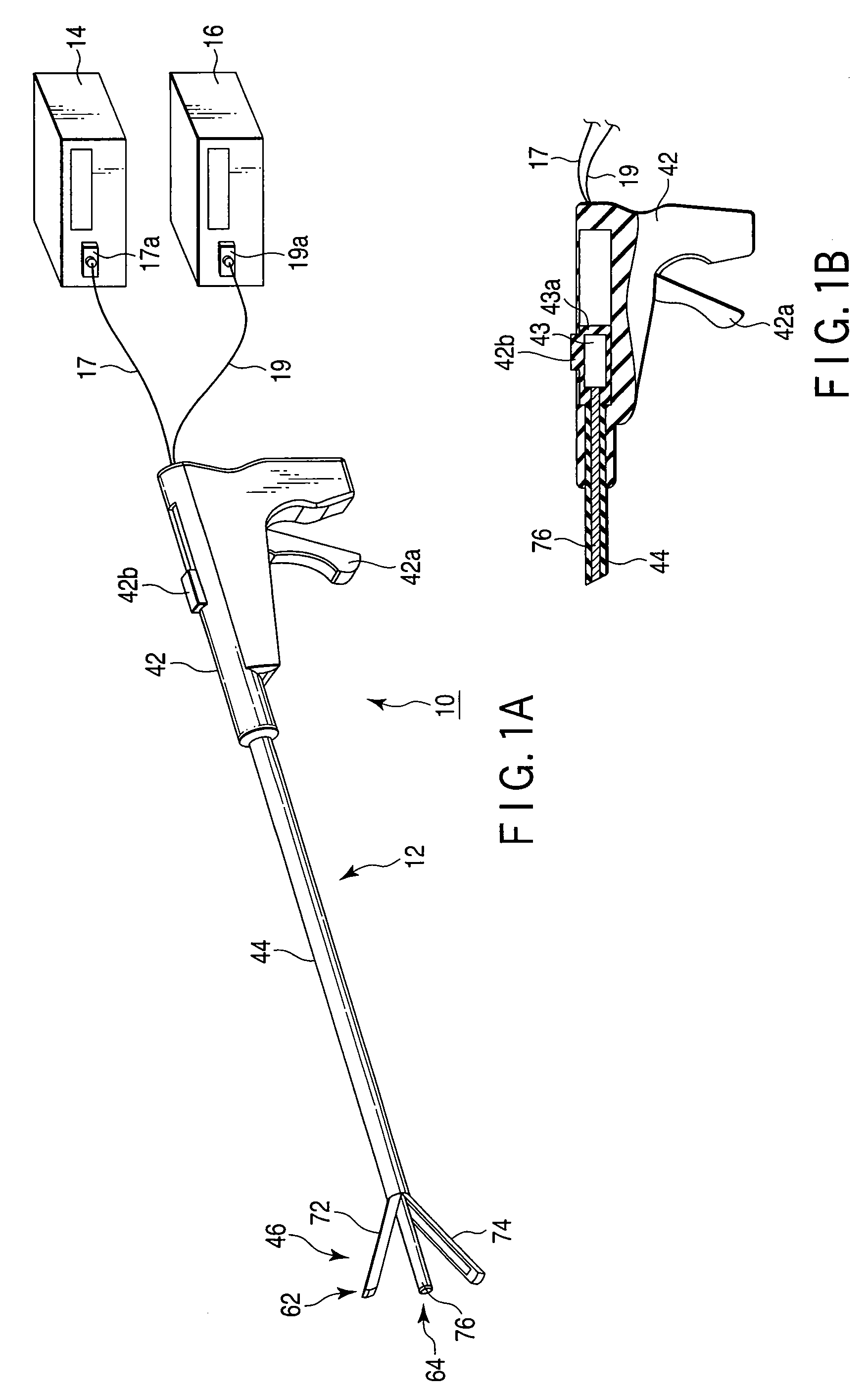
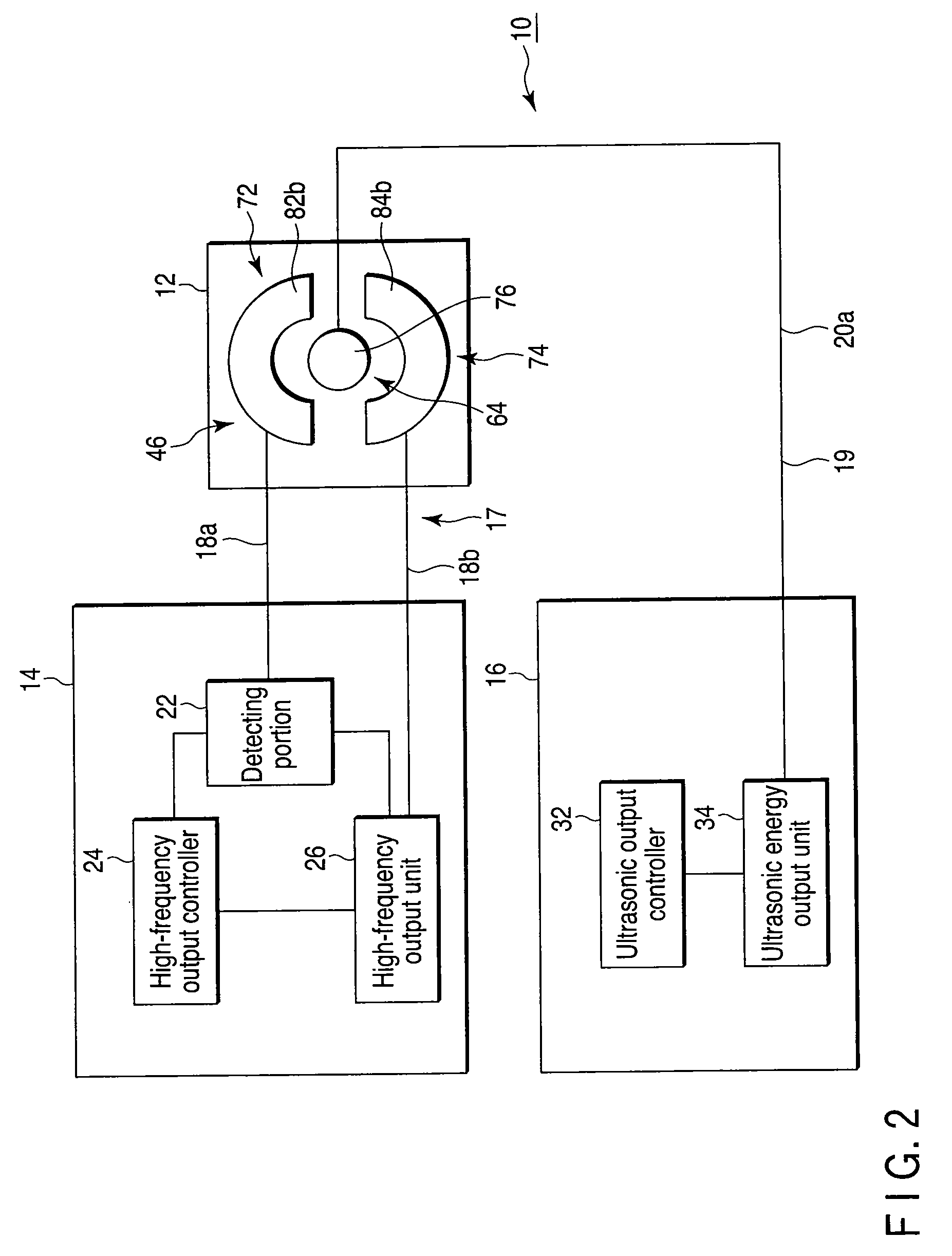
[0058]As shown in FIG. 1A and FIG. 2, a medical treatment apparatus 10 includes the energy treatment instrument (medical treatment instrument) 12, a high-frequency energy source 14 for providing high-frequency energy to the energy treatment instrument 12, and an ultrasonic energy source 16 for providing ultrasonic energy to the energy treatment instrument 12. The medical treatment apparatus 10 is connected to the high-frequency energy source 14 by a connector 17a of a cable 17 extending from the energy treatment instrument 12. The medical treatment apparatus 10 is connected to the ultrasonic energy source 16 by a connector 19a of a cable 19 extending from the energy treatment instrument 12.

[0059]As shown in FIG. 2, the high-frequenc...

second embodiment

[0130]Next, a second embodiment is described with FIG. 11 to FIG. 15. This embodiment is a modification of the first embodiment, and the same parts as the parts described in the first embodiment are provided with the same numerals and are not described in detail.

[0131]As shown in FIG. 11 and FIG. 12, the ultrasonic probe 76 (see FIG. 1A to FIG. 3D) which can be provided between first and second holding members 72, 74 is removed, and a cylindrical probe (hereinafter referred to as an ultrasonic suction probe) 176 is provided instead which can transmit ultrasonic vibrations and which can suck, for example, removed living tissues through its internal portion (suction passage 176a).

[0132]A medical treatment apparatus 10 includes an energy treatment instrument (treatment instrument) 12 called a handpiece, and a high-frequency energy source 14, an ultrasonic energy source 16, and a fluid feeding / suction unit 102.

[0133]The fluid feeding / suction unit 102 includes a bag 112 containing a phys...

third embodiment

[0160]Next, a third embodiment is described with FIG. 16 to FIG. 19B. This embodiment is a modification of the first embodiment, and the same parts as the parts described in the first embodiment are provided with the same numerals and are not described in detail.

[0161]As shown in FIG. 16 to FIG. 17D, the ultrasonic probe 76 which can be provided between first and second holding members 72, 74 is removed, and a rod high-frequency electrode (energy emitter) 276 is provided instead.

[0162]As shown in FIG. 16, a high-frequency energy source 14 of a medical treatment apparatus 10 includes a detecting portion 22, a high-frequency output controller 24, a high-frequency output unit 26, a switching unit 202 and a user interface 204.

[0163]The switching unit 202 is connected to the detecting portion 22 and to an energy treatment instrument 12. The switching unit 202 closes / opens a circuit between the first electrode 82b, the second electrode 84b and the rod electrode 276, and the energy treatme...


PUM


Abstract

A medical treatment apparatus includes an energy source which applies energy to living tissues, a first treating portion which joins the living tissues together, a second treating portion which is interposed between the living tissues and which removes surface portions of tissues in the joint surfaces of the living tissues, a detecting portion, and a controller. The first treating portion includes at least a pair of holding members having holding surfaces to hold the living tissues, and an energy output unit which is provided on the holding surfaces of the holding members and which join the living tissues together when energy is applied thereto from an energy source. The detecting portion detects biological information regarding the living tissues held by the pair of holding members. The controller controls outputs from the energy output unit in accordance with the biological information regarding the living tissues obtained by the detecting portion.

Description

BACKGROUND OF THE INVENTION[0001]1. Field of the Invention[0002]This invention relates to a medical treatment apparatus, a medical treatment instrument and a treatment method for living tissue using energy that are capable of joining a plurality of living tissues together using energy.[0003]2. Description of the Related Art[0004]In surgical operations including an abdominal operation and a laparoscopic operation, a tubular tissue or organ of, for example, a blood vessel may be sealed, or other tissues may be joined together. For example, a suture or clip is used to seal the blood vessel to be disjoined. A suture or staple is used to seal or anastomose cut ends of a digestive tract. In addition, techniques using energy have been in use recently. A high-frequency device or ultrasonic device is constantly used to seal a blood vessel, and moreover, other devices used for thicker living tissues are also making progress. In such a procedure, living tissues are held with a forceps-shaped d...

Claims


Application Information

Patent Timeline
IPC IPC(8): A61B18/04
CPCA61B17/320092A61B18/085A61B18/1206A61B18/1445A61B18/1482A61B2018/00702A61B2018/00875A61B2018/1472A61B2218/002A61B2218/007A61N7/02A61B2017/320095
Inventor SAKAO, SATOMIIIDA, KOJI
Owner OLYMPUS MEDICAL SYST CORP
Why Eureka
Try Eureka