Intervertebral implant comprising dome-shaped joint surfaces

a technology of intervertebral implants and joint surfaces, which is applied in the field of artificial intervertebral implants, can solve the problems of limiting the natural function of the spine, intervertebral disks, and discomfort for patients, and achieves the effect of no

Active Publication Date: 2006-10-12
SYNTHES USA
View PDF28 Cites 66 Cited by
  • Summary
  • Abstract
  • Description
  • Claims
  • Application Information

AI Technical Summary

Benefits of technology

[0006] Thus it is desirable to produce a device for artificial replacement of an intervertebral disc, that has a joint that can execute a rotary movement, can be pre-assembled and where the joint parts can be held together with a clearance by joinin

Problems solved by technology

Intervertebral disks often become damaged creating discomfort for a patient.
It is known that partial or total removal of a damaged intervertebral disk may alleviate some of this discomfort but may limit the natural function of the spine.
A disadvantage of this known intervertebral implant is that although the two cover plates are connected with a joint part each, the joint parts are not held together.
This requires the implant to be assembled by the surge

Method used


Image

  • Intervertebral implant comprising dome-shaped joint surfaces
  • Intervertebral implant comprising dome-shaped joint surfaces
  • Intervertebral implant comprising dome-shaped joint surfaces

Examples


Embodiment Construction

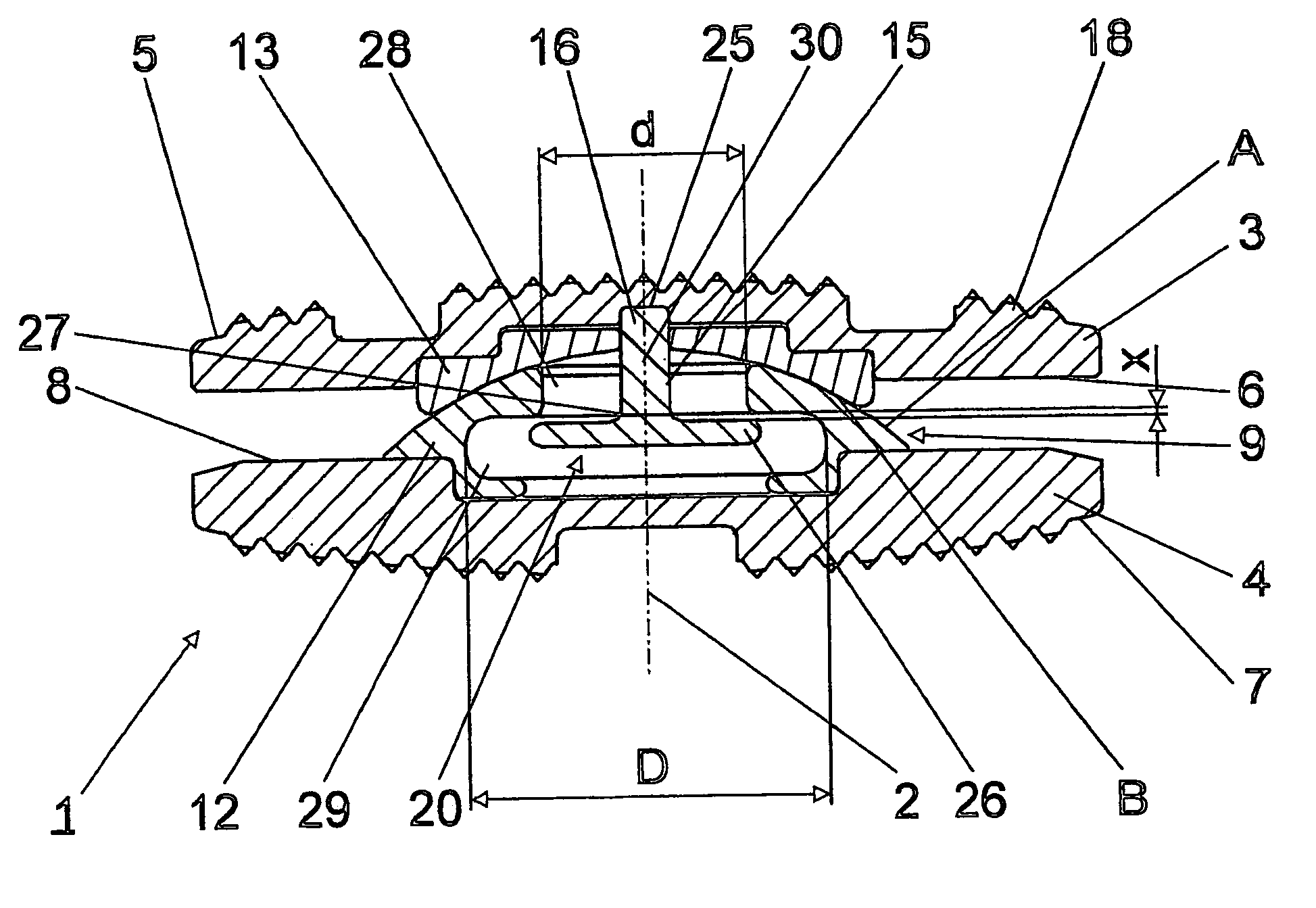
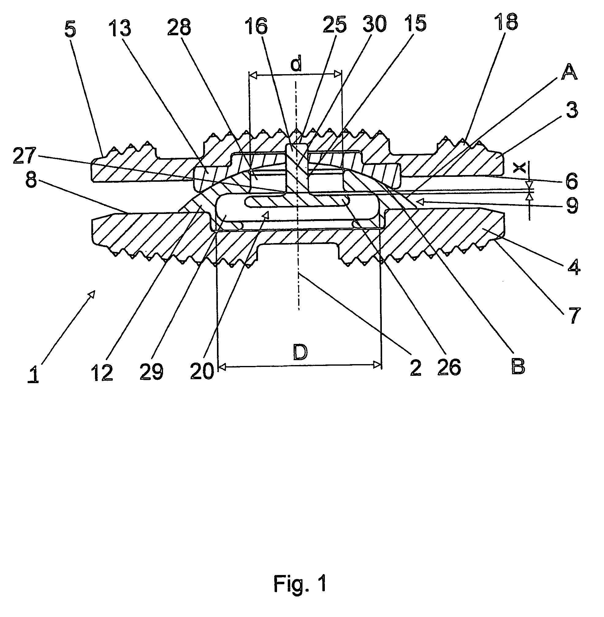
[0024] The embodiment of the intervertebral implant 1 illustrated in FIGS. 1-4 comprises a central axis, a top part 3, a bottom part 4, a joint 9 and an anchoring element 15. The top part 3 comprises a top apposed surface 5 that intersects a central axis 2 wherein the top apposed surface 5 is adapted to be placed adjacent and preferably in contact with a vertebra located above the site of a removed intervertebral disk. The bottom part 4 comprises a bottom apposed surface 7 that intersects a central axis 2 wherein the bottom apposed surface 7 is adapted to be placed adjacent and preferably in contact with a vertebra located above the site of a removed intervertebral disk. The joint 9 intersects the central axis and is provided between the top part 3 and bottom part 4, for the articulated joining of the top part 3 and bottom part 4. The joint 9 has a two-part construction comprising a convex joint part 12 and a joint shell 13. The convex joint part 12 is shaped as a partial spherical ...


PUM

PropertyMeasurementUnit
Fractionaaaaaaaaaa
Fractionaaaaaaaaaa
Fractionaaaaaaaaaa

Abstract

An intervertebral implant with a central axis, a top part, a bottom part, a joint comprising a joint part and a joint shell, and a joining means. The top part has a top apposed surface that is suitable for placing it on a vertebra situated above it; The bottom part has a bottom apposed surface, that is suitable for placing it on a vertebra situated below it. One of the two parts is operatively associated with a convex joint part and the other part to a matching joint shell. The joint part and the joint shell are mounted against one another in a sliding manner such that the top part and the bottom part can rotate relative to one another at least about one axis of rotation. The joining means holds the top part and the bottom part together without impairing the capability of the joint to pivot while allowing a clearance between the joint part and the joint shell.

Description

CROSS-REFERENCE TO RELATED APPLICATION [0001] This application is a continuation of International Patent Publication PCT / CH2003 / 000495, filed Jul. 22, 2003, which is incorporated by reference herein in its entirety. FIELD OF THE INVENTION [0002] The present invention relates to an intervertebral implant and, more particularly, to an artificial intervertebral implant. BACKGROUND OF THE INVENTION [0003] Intervertebral disks often become damaged creating discomfort for a patient. It is known that partial or total removal of a damaged intervertebral disk may alleviate some of this discomfort but may limit the natural function of the spine. Thus, nowadays following the removal of a damaged, natural intervertebral disk or a damaged nucleus pulposus of a natural intervertebral disk, an implant or prosthesis is placed in the intervertebral space between the two vertebra adjacent to the site of removal. The aim of implanting such devices is to bring about an as natural state as possible, par...

Claims


Application Information

Patent Timeline
IPC IPC(8): A61F2/44A61F2/00A61F2/30A61F2/46
CPCA61F2/4425A61F2310/00748A61F2002/30354A61F2002/30662A61F2002/30685A61F2002/30828A61F2002/30843A61F2002/30879A61F2002/30884A61F2002/30892A61F2002/30904A61F2002/3093A61F2002/443A61F2220/0033A61F2310/00023A61F2310/00029A61F2310/00293A61F2310/00574A61F2/4611
Inventor LECHMANN, BEATBURKI, ROGERFRIGG, ROBERT
Owner SYNTHES USA
Why Eureka
Try Eureka