Digital television and channel editing method thereof
a digital television and channel technology, applied in the field of digital television and channel editing methods, can solve the problems of waste of time and energy for users to roll through channel numbers, and the inability to efficiently achieve the channel editing process
- Summary
- Abstract
- Description
- Claims
- Application Information
AI Technical Summary
Benefits of technology
Problems solved by technology
Method used
Image
Examples
first embodiment
[0048]FIG. 4A is a block diagram of a digital TV according to the present invention.
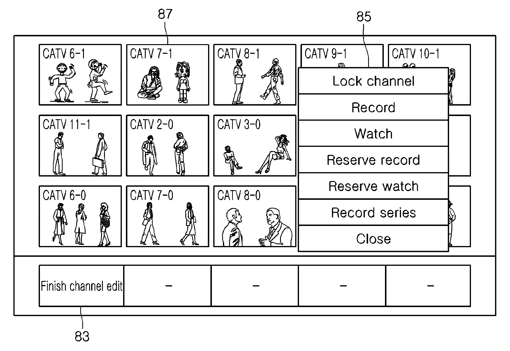
[0049]Referring to FIG. 4A, the digital TV according to the first embodiment of the present invention includes: first and second tuners 101 and 102 for tuning to different broadcast channels among the broadcast signals inputted through one or more antennas according to a user's request; a switching unit 103 for selectively outputting the broadcast signals tuned by the first and second tuners 101 and 102; a first signal processor 107 for processing the broadcast signal of the first tuner 101 selected by the switching unit 103 into a signal that can be displayed on a display unit 110 such as a screen; a second signal processor 108 for processing the broadcast signal of the second tuner 102 selected by the switching unit 103 into a signal that can be displayed on the display unit 110; a key input unit (user input unit) 104 for inputting request commands of a user and any other inputs; a microcomputer (c...
second embodiment
[0071]FIG. 6 is a block diagram of a digital TV according to the present invention. In this embodiment, a single tuner is used to tune to all available channels including any user selected channel.
[0072]Referring to FIG. 6, the digital TV according to the second embodiment of the present invention includes: a single tuners 201 for tuning to different broadcast channels among the broadcast signals inputted through one or more antennas according to a user's request; a signal processor 207 for processing the broadcast signals of the tuner 201 into signals that can be displayed on a display unit 110; a key input unit (user input unit) 104 for inputting request commands of a user and any other inputs; a microcomputer (controller) 105 for outputting control signals in response to the commands of the user (e.g., a channel edit command, a channel edit execution command, etc.); a storage or memory 106 for storing standing (non-moving) pictures of channels tuned by the tuner 201 and set chann...
third embodiment
[0075]FIG. 7 is a block diagram of a digital TV according to the present invention.
[0076]Referring to FIG. 7, the digital TV according to the third embodiment of the present invention includes: a plurality of tuners 301 each for tuning to a different broadcast channel among the broadcast signals inputted through one or more antennas according to a user's request; a switching unit 303 for selectively outputting the broadcast signals tuned by the tuners 301; a plurality of signal processors 307 for processing the broadcast signals of the tuners 301 selected by the switching unit 303 into signals that can be displayed on a display unit 110; a key input unit (user input unit) 104 for inputting request commands of a user and any other inputs; a microcomputer (controller) 105 for outputting control signals in response to the commands of the user (e.g., a channel edit command, a channel edit execution command, etc.) and controlling the elements of the digital TV; a storage or memory 106 fo...
PUM
 Abstract
Description
Claims
Application Information
 - R&D
- Intellectual Property
- Life Sciences
- Materials
- Tech Scout
- Unparalleled Data Quality
- Higher Quality Content
- 60% Fewer Hallucinations
Browse by: Latest US Patents, China's latest patents, Technical Efficacy Thesaurus, Application Domain, Technology Topic, Popular Technical Reports.
© 2025 PatSnap. All rights reserved.Legal|Privacy policy|Modern Slavery Act Transparency Statement|Sitemap|About US| Contact US: help@patsnap.com


