
Landscape Edger With Adjustable Connection Mechanism

Active Publication Date: 2010-07-29
OLDCASTLE PRECAST
View PDF54 Cites 18 Cited by
  • Summary
  • Abstract
  • Description
  • Claims
  • Application Information

AI Technical Summary

Benefits of technology

[0007]It is thus one aspect of the present invention to provide an edger that is flexible and can be bent to accommodate a paving scheme in a non-linear direction to accommodate any variety of shapes and geometric configurations. More specifically, the edger of one embodiment is sufficiently rigid, but bendable such that it can be formed into a plurality of different shapes and configurations by utilizing a series of continuous or non-continuous arcuate members that extend from a vertical wall (also referred to in the art as a “plate”). In a further aspect of the present invention, the rigidity (i.e., bending stiffness) of the edger can be selectively modified by altering the thickness, height, curvature, and number of the plurality of arcuate members that extend from the vertical wall of the edger. Alternatively, in some embodiments, the bending stiffness of the edger can be modified by decreasing the width of a base member that is associated with a lower edge of the vertical wall.
[0008]It is another aspect of the present invention to provide a coupling mechanism that allows two or more edgers to be selectively interconnected and securely maintained. More specifically, in one embodiment, a first coupling device is positioned on one end of the edger. A plurality of complimenting second coupling members are positioned at predetermined locations along the length of the edger for interconnection with the first coupling device to form either a continuous length of edgers. Alternatively, in one embodiment a coupling device is provided which allows two distinct edgers to be interconnected at about a 90° angle.

Problems solved by technology

The prior art edgers are simplistic, yet tend to move over time and can be dangerous to children and pets as they often possess a sharp upper edge.
One drawback of these more rigid edgers is their increased stiffness, thereby rendering the edger difficult to use to define a non-linear boundary.
Further, many prior art edgers do not interconnect securely to form a continuous edging surface, which makes the mate between two adjacent edgers susceptible to movement and detachment.
Finally, without a secure method of quickly interconnecting two or more edgers, installation time and subsequent costs are increased, especially in commercial landscaping applications.

Method used


Image

  • Landscape Edger With Adjustable Connection Mechanism
  • Landscape Edger With Adjustable Connection Mechanism
  • Landscape Edger With Adjustable Connection Mechanism

Examples


Embodiment Construction

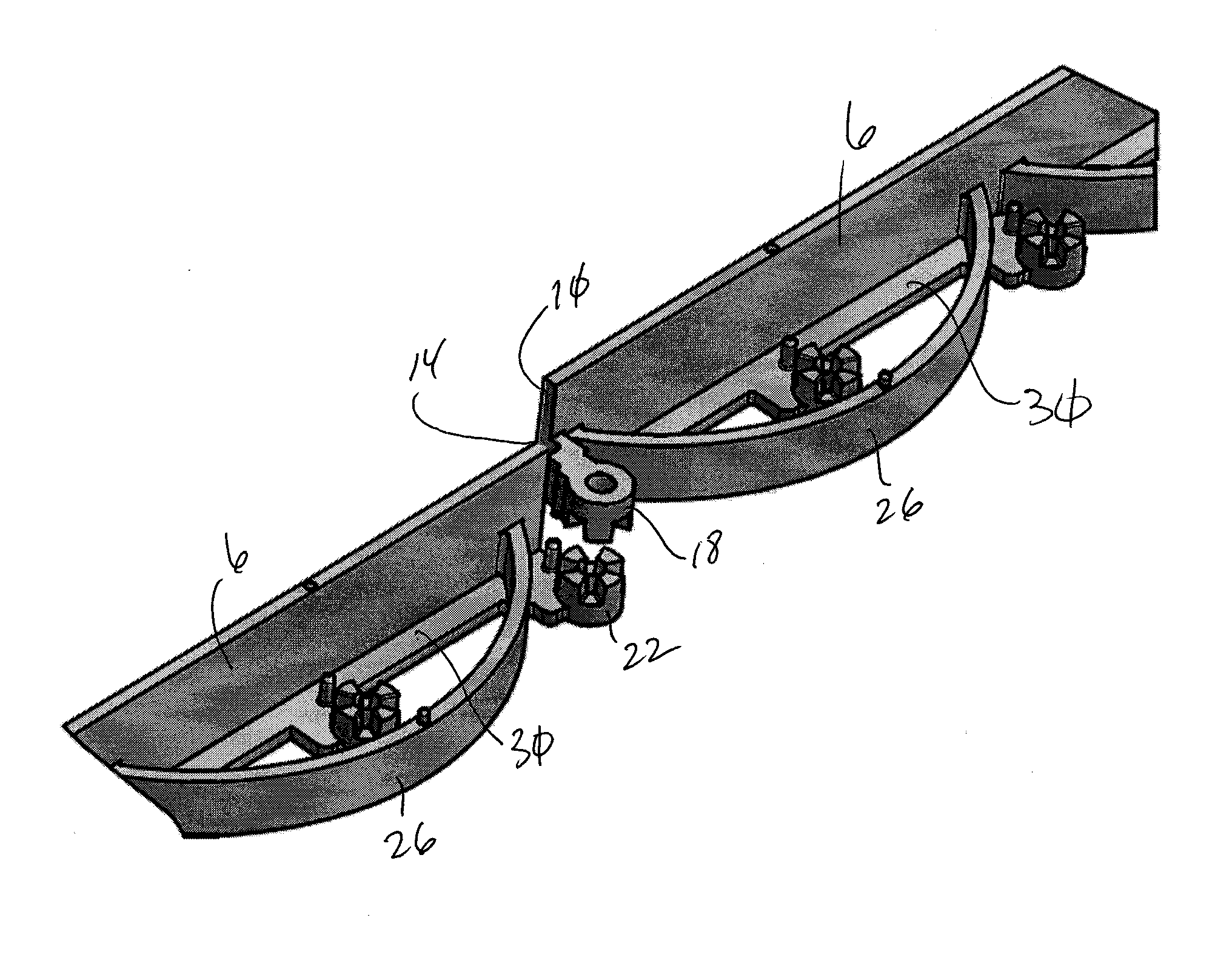
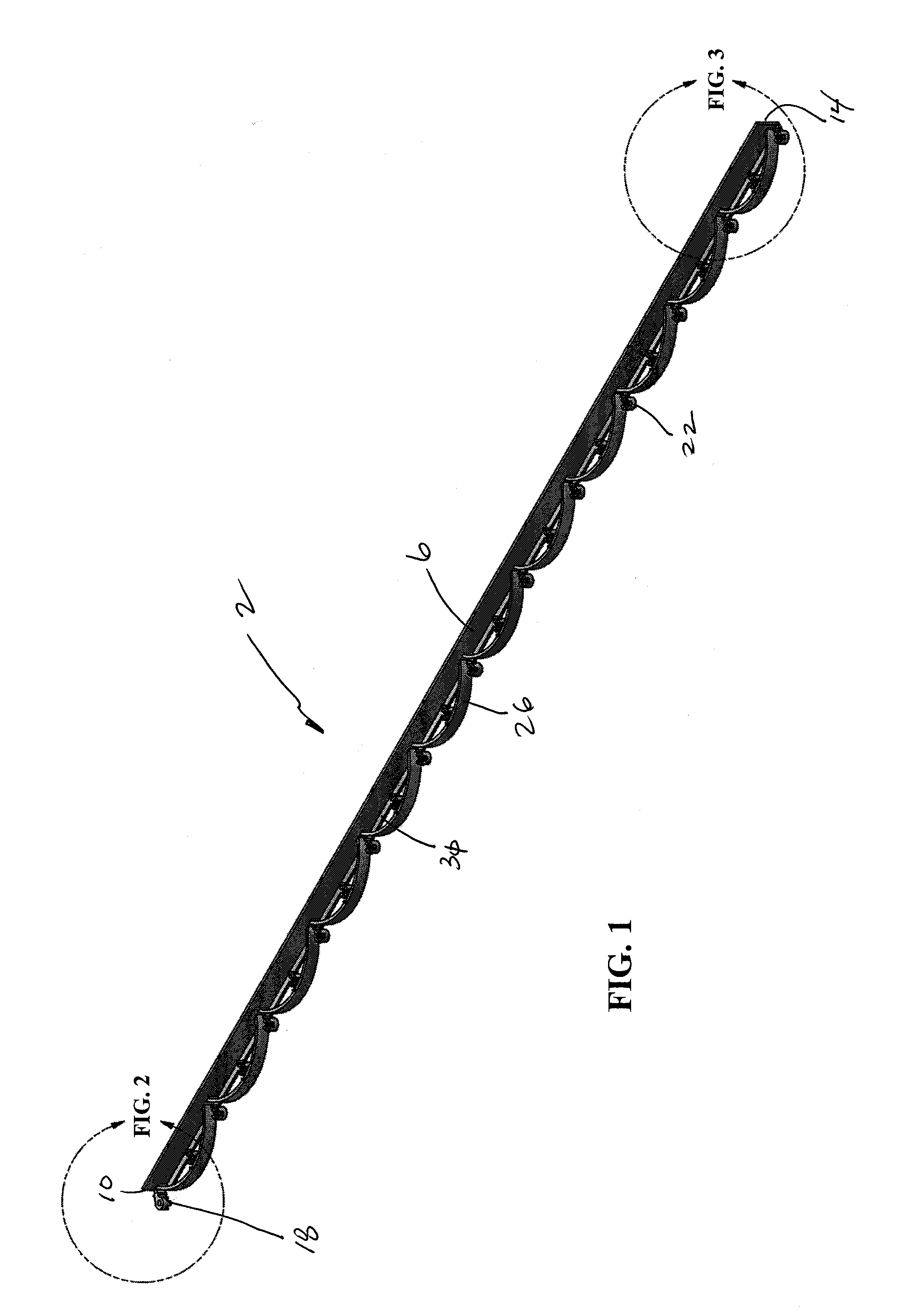
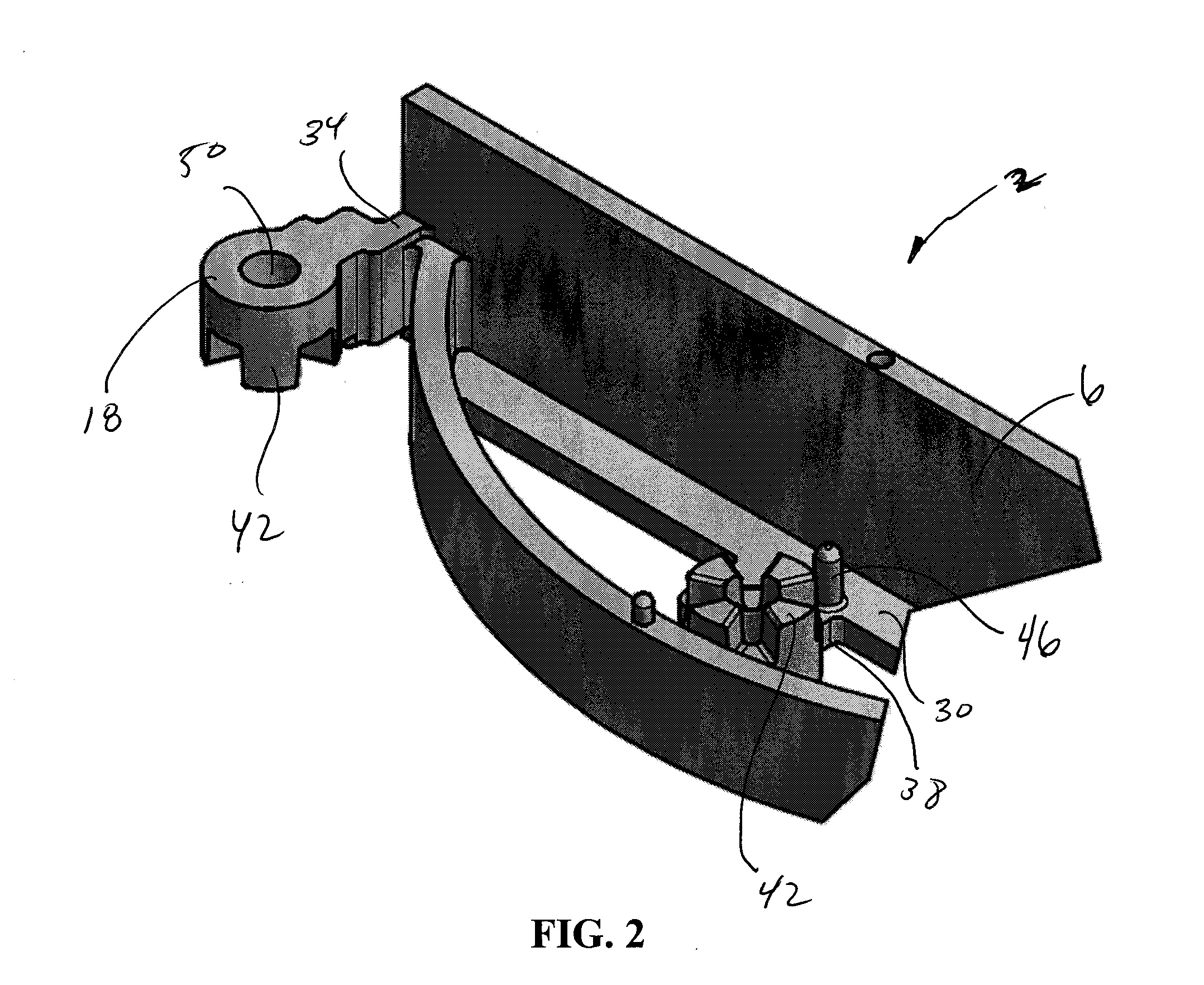
[0079]Referring now to FIGS. 1-9, an edger 2 of one embodiment of the present invention is shown. More specifically, this embodiment comprises a substantially vertical wall 6 defined by a first end 10 and a second end 14. An upper attachment member 18 is associated with the first end 10 and a lower attachment member 22 is associated with the second end 14. A plurality of lower attachment members 22 are also positioned between the first end 10 and the second end 14. Further, some embodiments of the present invention employ one or more arcuate members 26 that are positioned between the first end 10 and the second end 14 of the edger 2. The wall 6 is adapted to engage a portion of pavers on a first surface, and a footer 30 may also be included that extends from a second surface of the vertical wall 6 that rests on the ground adjacent to the pavers to provide additional stability.

[0080]The arcuate members 26 extend from a rear surface of the vertical wall 6, and are provided for additio...


PUM


Abstract

An edger is provided that includes a cylindrically shaped attachment member that includes at least one tooth for interlocking relationship with another attachment member. The interlocking relationship prevents relative motion between the attached edgers. The edger further comprises a plurality of arcuate members that help support the wall against the restrained pavers and which provide stiffness to the wall.

Description

[0001]This application claims the benefit of U.S. Provisional Patent Application Ser. No. 61 / 147,987, filed Jan. 28, 2009, is a Continuation-In-Part of U.S. patent application Ser. No. 29 / 350,744, filed Nov. 23, 2009, and a Continuation-In-Part of U.S. patent application Ser. No. 29 / 344,966, filed Oct. 7, 2009, the entire disclosures of which are incorporated by reference herein.FIELD OF THE INVENTION[0002]Embodiments of the present invention are generally related to members used to restrain paving stones or other common landscaping materials, and which maintain these materials at a predetermined location and configuration, and define boundaries therebetween.BACKGROUND OF THE INVENTION[0003]Edging devices (referred to herein as “edgers”) are used to define a specific boundary between a grass surface and a landscape surface such as gravel, brick, tile, rock, pavement and paving stones (hereinafter “pavers”). The edger provides a distinct border to prevent the movement or “creep” of t...

Claims


Application Information

Patent Timeline
IPC IPC(8): A01G1/08A01G9/28
CPCA01G9/28
Inventor FLYNN, REILLY JAMES
Owner OLDCASTLE PRECAST
Learn More