Drive Device

Active Publication Date: 2010-07-29
STABILUS
View PDF7 Cites 55 Cited by
  • Summary
  • Abstract
  • Description
  • Claims
  • Application Information

AI Technical Summary

Benefits of technology

[0030]So that the drive device can be operated conveniently, a sensor device comprises a internal gear, which is supported s

Problems solved by technology

The disadvantage of these drives, however, is that misalignments and axial offsets lead to

Method used


Image

  • Drive Device
  • Drive Device
  • Drive Device

Examples


Example

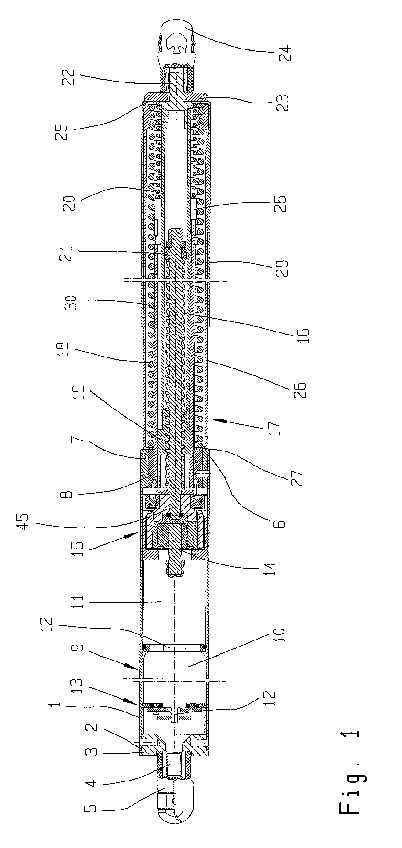
[0043]The drive device shown in FIG. 1 has a first housing tube 1 with a first end 2, wherein the first end 2 is closed off by a bottom piece 3. A threaded pin4 is formed on the bottom piece 3, and a first fastening device 5 in the form of a ball socket is screwed onto this pin. At the other end 6, i.e., the end opposite the first end 2, a sleeve 7, in which in turn a guide bush 8 is mounted with a press-fit, is arranged. Alternatively, however, it is also possible to design the sleeve 7 and the guide bush 8 as a one-piece unit.

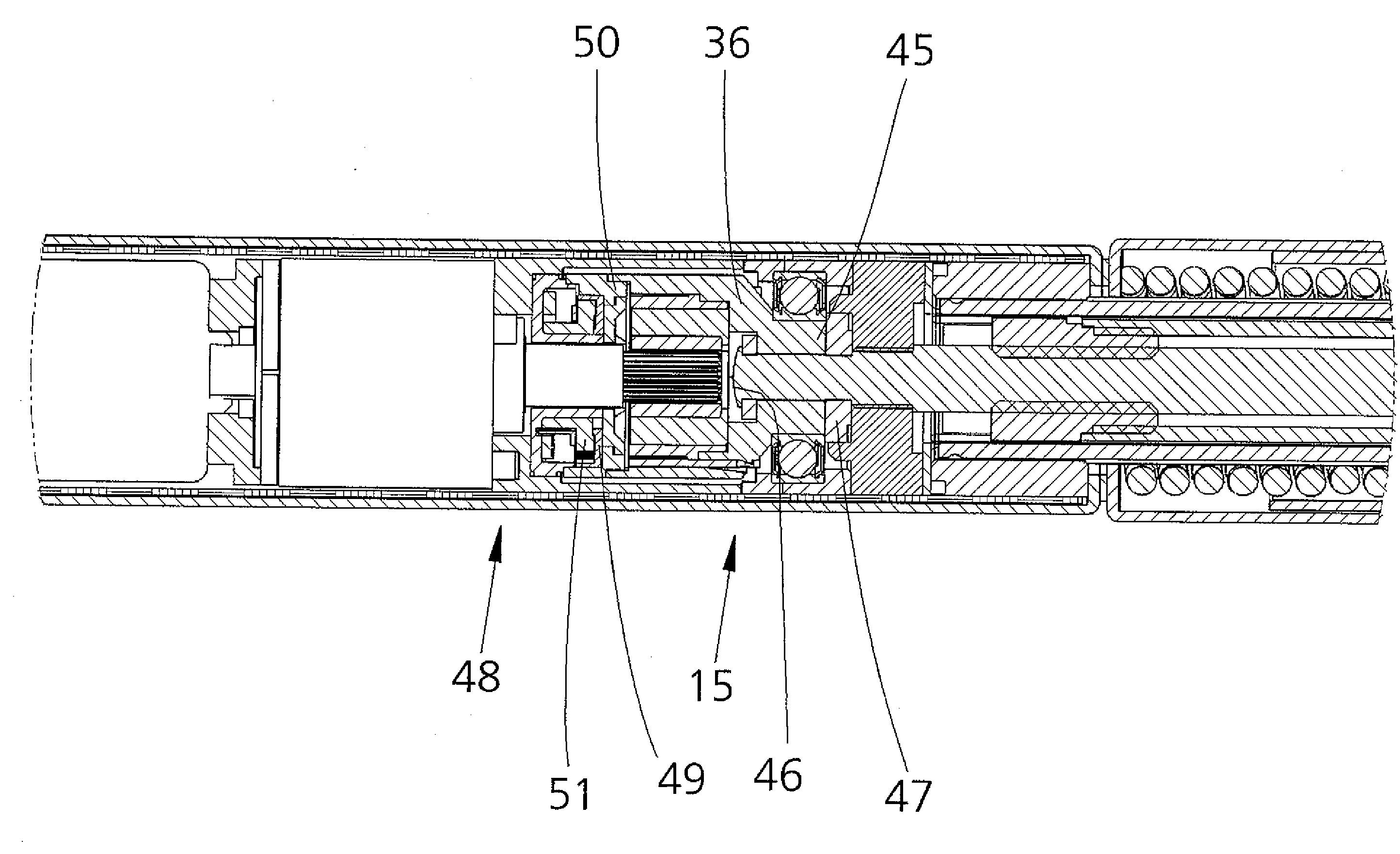
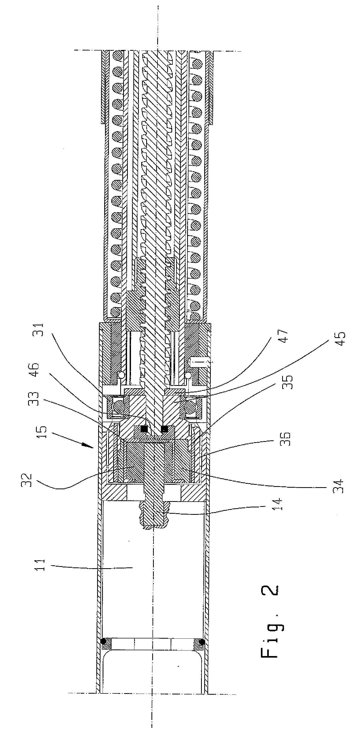
[0044]Next to the first end 2 of the first housing tube 1 is a rotary drive 9, which comprises an electric motor 10 and a gearbox 11. A drive shaft 12 projects out of each end of the electric motor 10. One end of this shaft drives a sensor device 13, and the other end drives the gearbox 11. On the side of the gearbox 11 facing away from the electric motor 10, a gear output shaft 14 extends toward the second end 6. A clutch device 15 is connected at one end to...


PUM


Abstract

A drive device includes a first fastening device (5), for connection to a stationary base part, especially a vehicle body, or to a movable part, especially a vehicle (hinged) lid or door; a second fastening device (24), for connection to the movable part or to the stationary base part; a spindle drive (17), which includes a threaded spindle (16) and a spindle nut (19) mounted on the threaded spindle (16) and capable of moving the first and the second fastening devices (5, 24) axially relative to each other; and a rotary drive (9), which rotates the spindle drive (17) by way of an overload safety device, wherein the nonrotatable connection between the two components can be released when a certain torque is exceeded, and wherein the overload safety device is formed by a clutch device (15), which comprises an inner part (32) connected to the rotary drive (9), which inner part rotates an intermediate part (34) by way of a damping element (33) and, by way of the intermediate part (34), rotates an outer part (36) connected to the spindle drive (17).

Description

BACKGROUND OF THE INVENTION[0001]1. Field of the Invention[0002]The present invention is directed to a drive device with a first fastening device, which can be connected to a stationary base part, especially a vehicle body, or to a movable part, especially a vehicle hinged lid or door; a second fastening device, which can be connected to the movable part or to the stationary base part; a spindle drive, comprising a threaded spindle and a spindle nut mounted on the threaded spindle and capable of moving the first and the second fastening devices axially relative to each other; and a rotary drive, which rotates the spindle drive by way of an overload safety device, wherein the nonrotatable connection between the two components can be released when a certain torque is exceeded.[0003]2. Description of the Related Art[0004]Many different variations of drives of this type are known. The disadvantage of these drives, however, is that misalignments and axial offsets lead to the generation o...

Claims


Application Information

Patent Timeline
IPC IPC(8): F16H25/20F16D7/02
CPCE05Y2201/216E05Y2201/25E05Y2900/546F16D7/044F16D7/048F16H25/2021F16H2025/2075E05Y2800/232E05Y2800/238E05F15/622Y10T74/18696Y10T74/18576
Inventor HILLEN, JORGRITTER, ANDREAS
Owner STABILUS
Why Eureka
Try Eureka