Light source device and projector
a light source device and projector technology, applied in the direction of point-like light sources, electrical components, lighting and heating apparatus, etc., can solve the problems of difficult to make the entire device small, difficult to improve the luminous efficiency, and the microwave may have an adverse effect on other electronic devices and a human body, so as to achieve excellent luminous efficiency and reduce leakage
- Summary
- Abstract
- Description
- Claims
- Application Information
AI Technical Summary
Benefits of technology
Problems solved by technology
Method used
Image
Examples
first embodiment
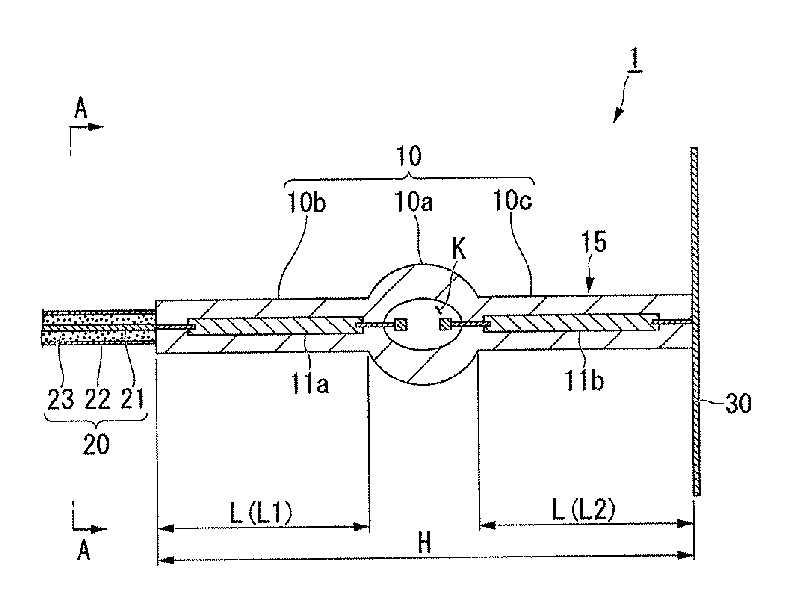
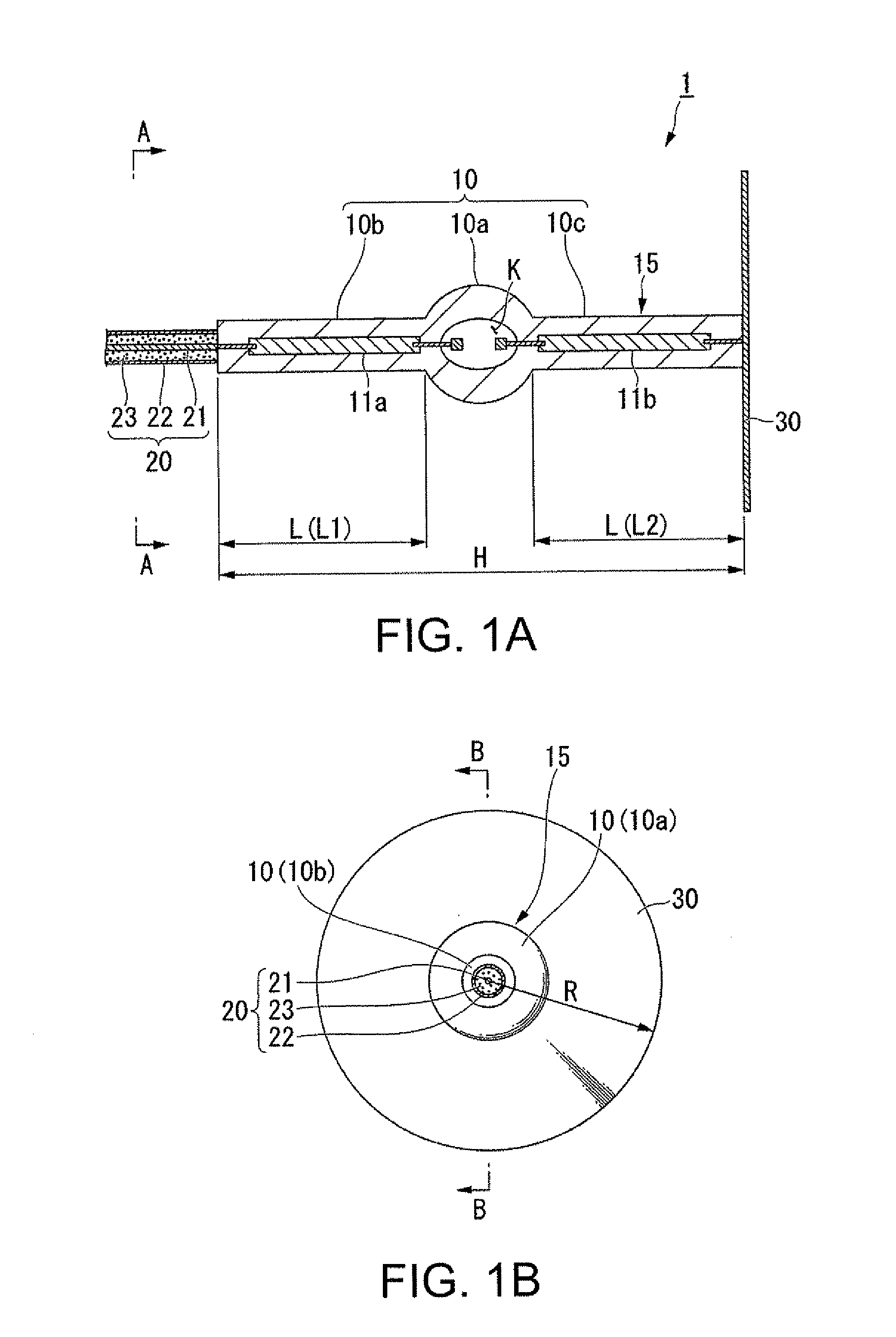
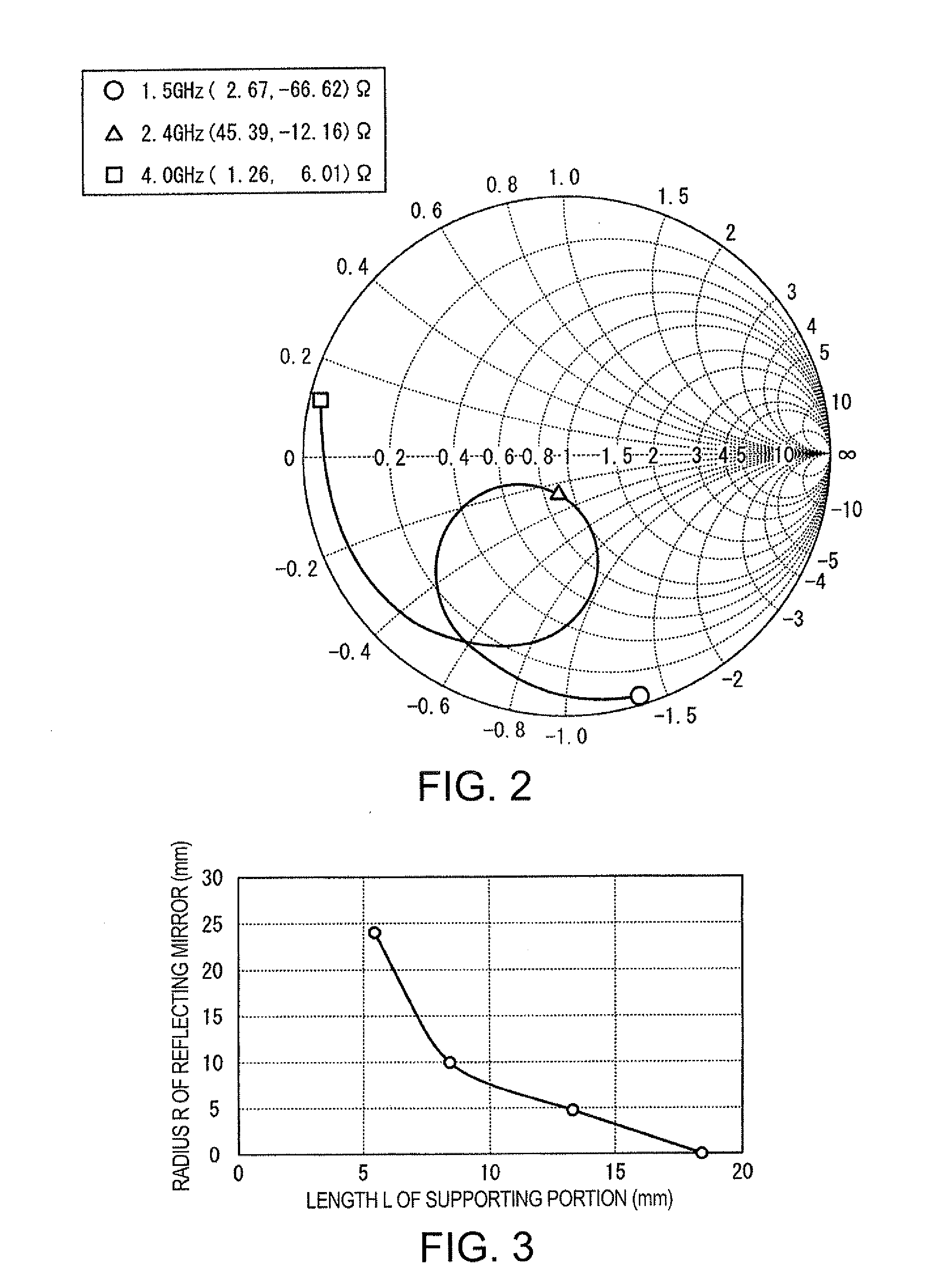
[0041]FIGS. 1A and 1B are schematic views showing a light source device according to a first embodiment of the invention. FIG. 1A is a sectional view taken along the line IA-IA of FIG. 1B. FIG. 1B is a sectional view taken along the line IB-IB of FIG. 1A. As shown in FIGS. 1A and 1B, a light source device 1 according to the present embodiment includes a microwave excitation lamp 15, a reflecting plate 30 connected to one side of the microwave excitation lamp 15, and a coaxial cable 20 connected to the other side of the microwave excitation lamp 15. A microwave power source (not shown) which outputs a microwave is connected to a side of the coaxial cable 20 which is opposite to the other side of the coaxial cable 20 connected to the microwave excitation lamp 15. The microwave excitation lamp 15 emits light by a microwave which is input from the microwave power source through the coaxial cable 20.
[0042]The microwave excitation lamp 15 includes a light-emitting tube 10 and a pair of el...
second embodiment
[0075]Next, a light source device according to a second embodiment of the invention will be described with reference to FIG. 4. FIG. 4 is a view showing the schematic configuration of a light source device 2. The light source device 2 according to the present embodiment is different from the light source device 1 described in the first embodiment in that a reflecting plate 31 has a saucer shape. The other points are the same as those in the first embodiment. Accordingly, the same components as in FIGS. 1A and 1B are denoted by the same reference numerals, and a detailed explanation thereof will not be repeated.
[0076]As shown in FIG. 4, in the light source device 2, the reflecting plate 31 has a saucer shape instead of the disk-like shape unlike the light source device 1 of the first embodiment. One side of the microwave excitation lamp 15, specifically, an end of the supporting portion 10c which is opposite to a side of the supporting portion 10c adjacent to the light-emitting porti...
third embodiment
[0078]Next, a light source device according to a third embodiment of the invention will be described with reference to FIG. 5. FIG. 5 is a view showing the sectional configuration of a light source device 2A obtained by providing a reflector 40 in the light source device 2. The light source device 2A according to the present embodiment is different from the light source device 2 described in the second embodiment in that the reflector 40 is provided. The other points are the same as those in the second embodiment. Accordingly, the same components as in FIG. 4 are denoted by the same reference numerals, and a detailed explanation thereof will not be repeated.
[0079]As shown in FIG. 5, the light source device 2A is formed by providing the reflector 40, which reflects light emitted from the light-emitting portion 10a and light reflected from the reflecting plate 31, in the light source device 2 of the second embodiment. The reflector 40 includes an insertion portion 40b, into which the ...
PUM
 Abstract
Description
Claims
Application Information
 - R&D
- Intellectual Property
- Life Sciences
- Materials
- Tech Scout
- Unparalleled Data Quality
- Higher Quality Content
- 60% Fewer Hallucinations
Browse by: Latest US Patents, China's latest patents, Technical Efficacy Thesaurus, Application Domain, Technology Topic, Popular Technical Reports.
© 2025 PatSnap. All rights reserved.Legal|Privacy policy|Modern Slavery Act Transparency Statement|Sitemap|About US| Contact US: help@patsnap.com


