Fully coherent modular microwave heating device

A microwave heating equipment and modular technology, applied in microwave heating, electric/magnetic/electromagnetic heating, electric heating devices, etc., can solve problems such as microwave energy loss, electromagnetic interference, and personal safety threats, so as to prevent energy loss and reduce Effect of microwave leakage and high overall efficiency

Inactive Publication Date: 2019-04-05
成都赛纳微波科技有限公司
View PDF12 Cites 0 Cited by
  • Summary
  • Abstract
  • Description
  • Claims
  • Application Information

AI Technical Summary

Problems solved by technology

At the frequency of the working microwave, for a microwave feeder, after selecting its position, shape, and polarization direction, it is very difficult to determine the intensity of excitation of hundreds of modes in the heating cavity. is also extremely complex
In large-scale microwave heating equipment, hundreds of magnetrons are required as microwave sources, so the number of corresponding microwave feed ports can be as many as hundreds! The complexity of the above problems is beyond people's imagination
[0010] Second, heating efficiency issues
Since the different magnetrons used in the heating chamber are independent of each other, the microwaves generated by them are irrelevant and their spectrums are independent of each other. For the microwaves generated by any magnetron, due to the hundreds of The amplitude and phase of the mode is difficult to control and may overflow from multiple other feed ports
Although large-scale microwave heating equipment can reduce the mismatch reflection of the microwave feeder by selecting the volume, shape and density of the material to be heated, the microwave overflow loss between multiple microwave feeders is difficult to avoid
[0013] Third, the energy leakage problem of large microwave heating equipment
Hundreds of microwave feed ports have different shapes, positions and polarization directions. In addition, the microwave signals fed from each feed port are irrelevant to each other, so that the serious energy leakage problem of microwave energy through the feed port and the discharge port leads to The loss of microwave energy, especially the electromagnetic interference to the environment caused by large-scale microwave heating equipment, even poses a threat to personal safety
In order to reduce energy leakage, it is often necessary to install a very long filter structure at the inlet and outlet, resulting in a great increase in the length of the equipment

Method used


Image

  • Fully coherent modular microwave heating device
  • Fully coherent modular microwave heating device
  • Fully coherent modular microwave heating device

Examples


Embodiment 1

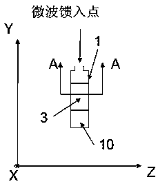
[0063] like Figure 1-3 shown.

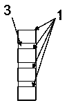
[0064] A fully coherent modular microwave heating device includes 5 heating modules. Any one of the heating modules includes a cavity 3, and above the cavity 3, four microwave feeding waveguides arranged along the X-axis communicate with the cavity 3 and feed microwave energy thereinto. Working microwaves from the outside first supply microwave energy to each microwave feed-in waveguide through each microwave feed-in point. Different heating modules are arranged along the Z axis, and the cavities 3 are sequentially connected along the Z axis.

[0065] On each of the heating modules, below the cavity 3, corresponding to each microwave feeding waveguide, a lower end short circuit whose cross section in the horizontal plane has the same shape as the corresponding microwave feeding waveguide is provided short-circuit waveguide. All short-circuit waveguides have the same size in the Y-axis direction.

[0066] It constitutes a fully coherent mod...

Embodiment 2

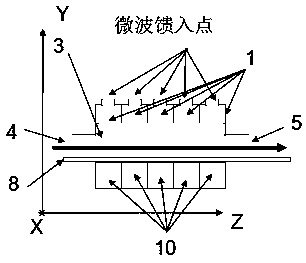
[0079] like Figure 4 and Figure 5 shown.

[0080] Compared with Embodiment 1, the only difference is that only one heating module is used, and only one microwave feeding waveguide 1 and short-circuit waveguide 10 are used in this heating module.

[0081] This implementation example can constitute a microwave oven. At this time, any feed port 4 and discharge port 5 may not be provided. The microwave door panel is arranged on one side of the -X axis of the cavity. Compared with general microwave ovens where working microwaves are fed from the side and the working microwaves in the microwave oven work in multiple modes, this implementation example feeds working microwaves from above. At the same time, by controlling the waveguide mode of the working microwave in the cavity to be the fundamental mode TE10 wave, the uniformity of the microwave in the X direction is guaranteed.

Embodiment 3

[0083] like Figure 4 and Image 6 shown.

[0084] Compared with Embodiment 2, the only difference is that four microwave feeding waveguides 1 are arranged along the X direction on one heating module. All the working microwaves fed into the waveguide are coherent waves with the same spectrum, the same amplitude and the same phase. It can be used as a fully coherent modular microwave heating device, and it can be used in occasions where the X direction is wider than that of Example 2.


PUM


Abstract

In the invention, a microwave heating device is divided into several heating modules connected in series along a Z axis. Only a fundamental mode TE10 mode is propagated in different microwave feedingwaveguides in each module, and the electric field direction only has an X-axis component. The working microwaves in the different microwave feeding waveguides in each heating module are coherent and share the same phase, and the isolation degree between the working microwave feeding waveguides of different heating modules is very high. Non-coherent microwave sources can be employed in different heating modules, or coherent microwave sources can be employed in different heating modules arranged along the Z axis, so the working microwaves in microwave feeding waveguides belonging to different heating modules which are aligned and adjacent along the Z axis have an equal amplitude and inverted phases, and TEn0 waves which are propagated in a -Y direction from top to bottom and along a Y axis from bottom to top are excited in a heating cavity composed of cavities belonging to different heating modules, n is an integer and is greater than or equal to 2. The device can be used for heating various materials or speeding up chemical reactions.

Description

technical field [0001] The present invention relates to microwave heating equipment. Specifically, it relates to a compact microwave heating device that utilizes a high-order mode to uniformly heat materials with high efficiency. Background technique [0002] Microwave energy can be used in place of various conventional heating methods. Microwave heating equipment uses microwave energy to heat a variety of materials, including but not limited to wood, grain, spices, dairy products. In the field of microwave chemistry, microwave energy is used to speed up various chemical reactions. Microwave energy is also used in the production of various materials such as nanomaterials and synthetic diamonds. [0003] In the traditional heating process, heat is conducted from the outside to the inside of the heated object, which belongs to surface heating, resulting in uneven temperature inside and outside the heated object. In microwave energy heating, microwaves are heated by the act...

Claims


Application Information

Patent Timeline
Patent Type & Authority Applications(China)
IPC IPC(8): H05B6/78H05B6/76H05B6/70H05B6/68
CPCH05B6/68H05B6/707H05B6/76H05B6/78
Inventor 王清源
Owner 成都赛纳微波科技有限公司
Why Eureka
Try Eureka