Collimating module and device for zero overfill illumination applications with beam width control

a technology of beam width control and illumination application, applied in the field of collimating modules, can solve the problems of less efficient illumination system and reduced light, and achieve the effect of reducing overfill ligh

Inactive Publication Date: 2010-07-29
SIGNIFY HLDG BV
View PDF8 Cites 27 Cited by
  • Summary
  • Abstract
  • Description
  • Claims
  • Application Information

AI Technical Summary

Benefits of technology

[0004]It is an object of the present invention to provide an improvement of the above techniques and prior art. More particularly, it is an object of the present invention to provide a collimating component for reducing overfill light.

Problems solved by technology

Such light, known as overfill light, reduces the amount of light onto the display scene and makes the illumination system less efficient.

Method used


Image

  • Collimating module and device for zero overfill illumination applications with beam width control
  • Collimating module and device for zero overfill illumination applications with beam width control
  • Collimating module and device for zero overfill illumination applications with beam width control

Examples


first embodiment

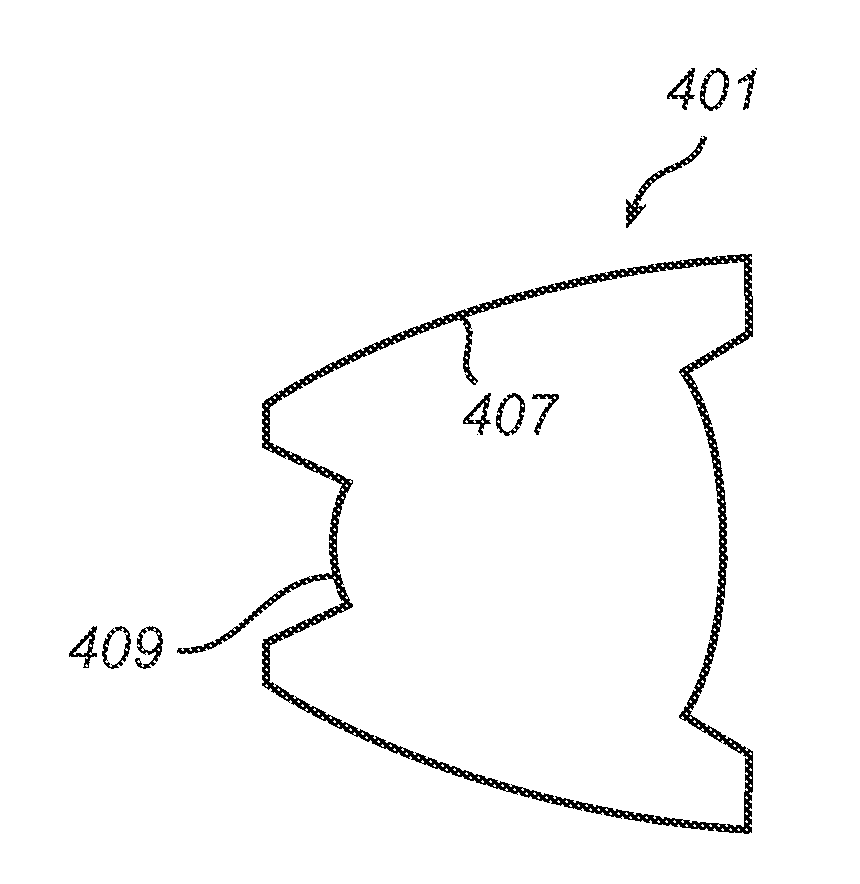
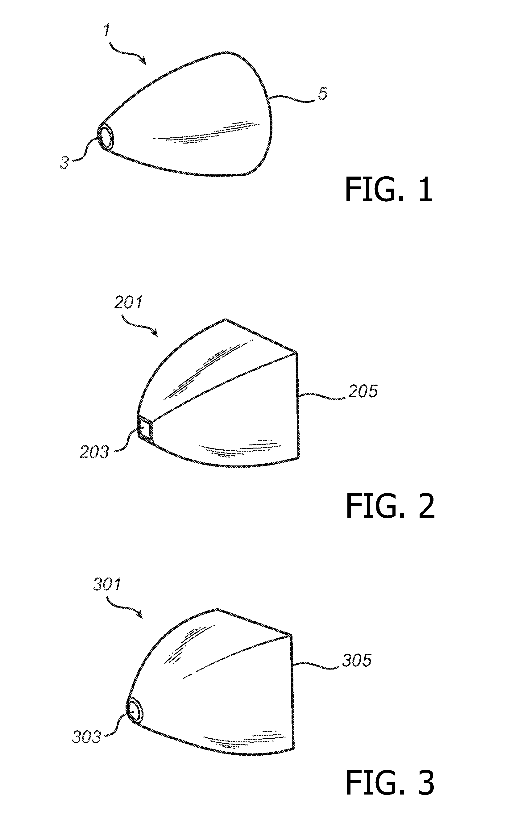
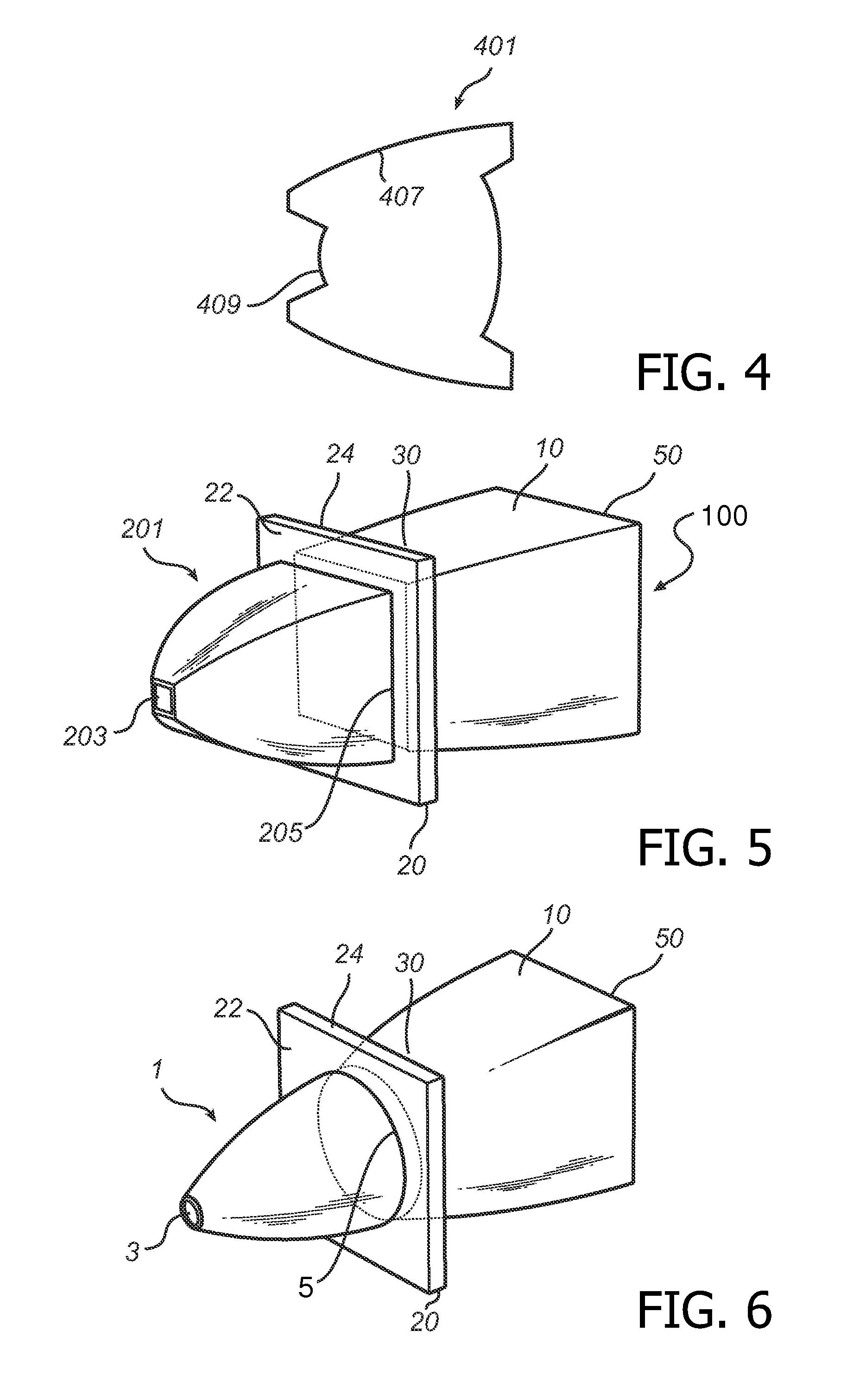
[0034]In FIG. 5, a collimating device 100 is shown. The collimating device 100 has a first collimator 201 and a collimating module 10. Between the first collimator 201 and the collimating module 10 a scattering component 20 is arranged, such that the exit side 205 of the first collimator 201 is connected to the entry side 30 of the collimating module. The entry side 203, 30 and the exit side 205, 50 of the first collimator 201 and the collimating module 10 are rectangular. A LED (not shown) is positioned adjacent to the entry side 203 of the first collimator 201 such that divergent light is incident on the entry side 203. The light propagates through the first collimator 201 such that the angular distribution of the light is changed. The angular distribution of the light extracted from the rectangular exit side 205 of the first collimator 201 may have an aspect ratio of 13°×10°, corresponding to a scene or object to be illuminated. For a square exit side 205, the angular distributio...

second embodiment

[0038]FIG. 6 shows a collimating device 100. The collimating device 100 has a first collimator 1 and a collimating module 10. Between the first collimator 1 and the collimating module 10 a scattering component 20 is arranged, such that the exit side 5 of the first collimator 1 is connected to the entry side 30 of the collimating module. The entry side 3 and the exit side 5 of the first collimator 1 are circular. The entry side 30 of the collimating module 10 is also circular, while the exit side 50 of the collimating module 10 is rectangular. A LED (not shown) is positioned adjacent to the entry side 3 of the first collimator 1 such that divergent light is incident on the entry side 3. The light propagates through the first collimator 1 such that the angular distribution of the light is changed. A scattering component 20 is positioned adjacent to the exit side 5 of the first collimator 1.

[0039]For tele illumination, the liquid crystal scatterer 20 is deactivated, and the illuminatio...


PUM


Abstract

A collimating module is presented. The collimating module comprises a rounded light entry side and a rectangular light exit side. A collimating device is also presented, and a method for providing collimated light. The collimating device comprises a first collimator having a light entry side and a light exit side, a scattering component having a light entry surface arranged adjacent to said light exit side, and a light exit surface. The collimating device further comprises a collimating module having a light entry side arranged adjacent to said light exit surface.

Description

FIELD OF THE INVENTION[0001]The present invention relates to a collimating module. It also relates to a collimating device for reducing overfill comprising a first collimator, a scattering component and such collimating module.TECHNICAL BACKGROUND[0002]Collimating components are widely used in different lighting applications. Such components can e.g. be compound parabolic concentrators, either based on total internal reflection or reflection by means of a reflective coating.[0003]Illumination systems for digital cameras may require control of beam width between small angles and wide angles in order to illuminate objects far away or nearby. One method to perform this is to make use of a scattering device. For small angles, the light emitted from a light source is collimated by a collimating component. The collimated light illuminates a small angle display scene. For wide angles, the light emitted from a light source is collimated by a collimating component and the collimated light is...

Claims


Application Information

Patent Timeline
Patent Type & Authority Applications(United States)
IPC IPC(8): G02B27/30G02B5/02
CPCG02B5/0278G02B5/3016G02B27/0927G02B19/0033G02B19/0028G02B19/0061G02B27/0994
Inventor PAULUSSEN, ELVIRA JOHANNA MARIATUKKER, TEUNIS WILLEM
Owner SIGNIFY HLDG BV
Why Eureka
Try Eureka