Charge mode control

a charge mode and control technology, applied in the direction of electric variable regulation, efficient power electronics conversion, instruments, etc., can solve problems such as low load

Active Publication Date: 2010-07-29
BANG & OLUFSEN
View PDF9 Cites 5 Cited by
  • Summary
  • Abstract
  • Description
  • Claims
  • Application Information

AI Technical Summary

Benefits of technology

[0015]With charge mode control, the second feedback loop measures and controls how much charge that is flowing through the resistor in each half period of switching. This charge is much more linear dependant to power than frequency. The fact that the change in charge instead of current and frequency is controlled is an important feature. If charge mode control by adding a second loop, is used, there are still some problems at low load. By using a combination of frequency control and charge mode control, this can be solved.
[0017]The degree of influence can be adjusted by changing the size of the two capacitors, hereby, it can be achieved that the change of operation mode starts its influence on demand, which is defined from the size of the capacitors. The output of the one or two capacitors can be connected to the input terminal of the oscillator part of the control circuit through at least one capacitor and resistor. Hereby, it can be achieved that the signal of the second feedback circuit is reduced to a value that can be used effectively to influence the charging and discharging of the capacitor connected to the oscillator part in the control circuit. This can be important in the design of new power supplies in that a very simple change of a component at a printed circuit board leads to a major change in function of the power supply.
[0018]Together with an L6598 or similar circuits, the second feedback needs an extra circuit. It contains an inverting amplifier, which output can be connected to the input terminal of the oscillator part through at least one capacitor and one resistor. Hereby, it can be achieved that the signal of the second feedback is inverted and amplified to a value that can be used effectively to influence the charging and discharging of the capacitor connected to the oscillator pin on the control circuit.

Problems solved by technology

If charge mode control by adding a second loop, is used, there are still some problems at low load.

Method used


Image

  • Charge mode control
  • Charge mode control
  • Charge mode control

Examples


Embodiment Construction

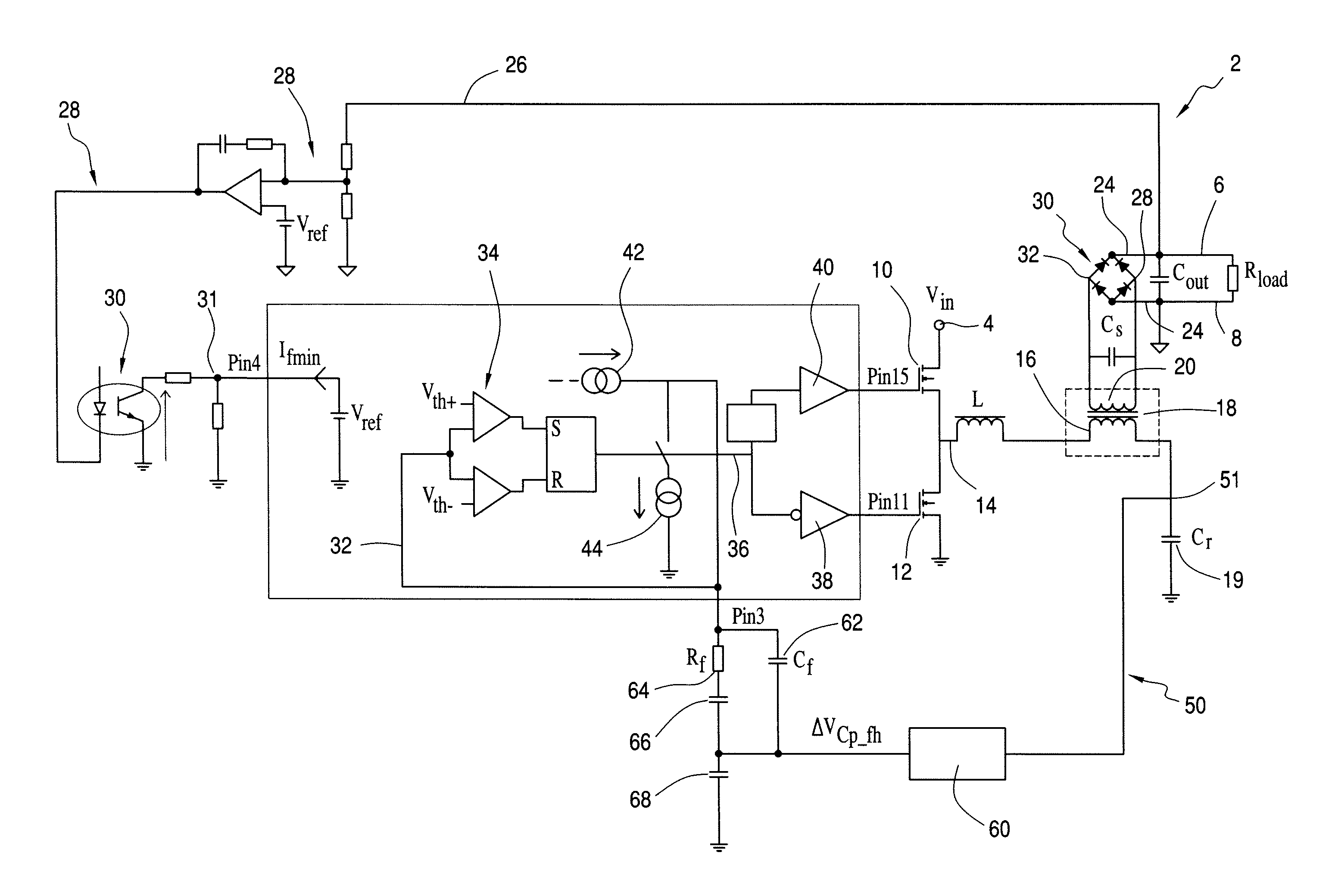
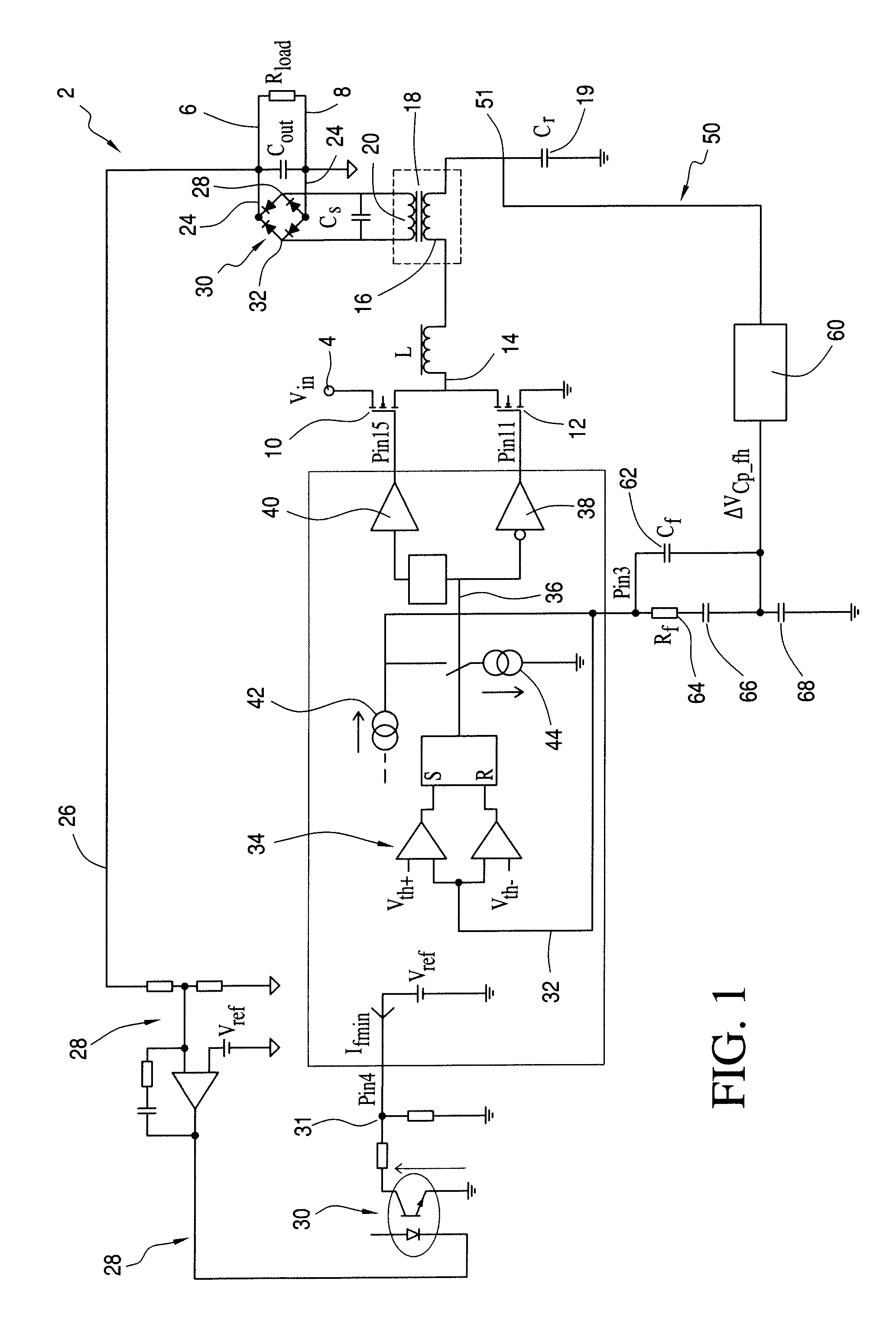
[0030]FIG. 1 describes a switch mode power supply 2 having a power input terminal 4 primarily for DC-power, and output terminals 6, 8 between which the power supply can deliver DC-power. Semiconductor switches 10, 12 are connected so that, if switch 10 is open, switch 12 is closed. Hereby, the voltage at the connection point 14 between the two semiconductor switches 10, 12 changes from zero and up to the input DC-voltage. The point 14 is connected to a first coil 15 from where current is flowing to a coil 16, which is part of a transformer 18. The coil 15 can be an integrated part of the transformer 18. The coil 16 is further connected to a capacitor 19. The transformer 18 also contains a coil 20, which is connected to rectifier means, which can be formed as a bridge rectifier 21 having an input terminal 22.

[0031]A rectified DC power is delivered at the output 24 towards the output terminals 6, 8, between which a capacitor C-out and a resistor R-load are shown. A feedback signal 26 ...


PUM


Abstract

An apparatus and a method for converting power from a power input to an DC output voltage or current, which apparatus has a serial resonance converter, where a first feedback circuit is connected from the output terminal to an error amplifier, where the apparatus further has a second feedback circuit with at least one first resistor that is connected to a coil and to ground, which second feed back circuit connects the line between the first resistor and the coil and towards an inverting integrator, the output of which is connected through a second capacitor to a second input at a control circuit. As a result, the oscillating frequency is under influence of a signal that depends on the voltage generated in the resistor connected in serial to the coil or transformer.

Description

CROSS-REFERENCE TO RELATED APPLICATION[0001]This application is a Continuation-in-Part of co-pending application Ser. No. 10 / 595,706, the entirety of which is incorporated herein by reference.BACKGROUND OF THE INVENTION[0002]1. Field of the Invention[0003]The present invention relates to an apparatus and a method for converting power from a power input to an DC output voltage or current, which apparatus comprises a serial resonance converter containing at least two serial coupled semiconductor switches having a common output terminal connected to at least one first coil which coil can be a part of a transformer having a second winding connected to a rectifier means, which rectifier means has its output connected to output terminals, where a first feedback circuit is connected from the output terminal to an error amplifier, which error amplifier is connected to an input at a control circuit, which output is connected over driver means to the input of the semiconductor switches, where...

Claims


Application Information

Patent Timeline
Patent Type & Authority Applications(United States)
IPC IPC(8): H02M3/335
CPCH02M3/33507Y02B70/16H02M2001/0032H02M3/3376H02M1/0032Y02B70/10
Inventor CHRISTENSEN, SOEREN KJAERULFF
Owner BANG & OLUFSEN
Why Eureka
Try Eureka