
Method for detecting the presence of spread spectrum signals

a spread spectrum and signal detection technology, applied in the field of blind or semiblind detection of spread spectrum signals, can solve the problems of not being able to obtain this information reliably, and not being able to determine with a low error rate whether a spread spectrum signal is absen

Active Publication Date: 2010-07-29
COMMISSARIAT A LENERGIE ATOMIQUE ET AUX ENERGIES ALTERNATIVES
View PDF4 Cites 2 Cited by
  • Summary
  • Abstract
  • Description
  • Claims
  • Application Information

AI Technical Summary

Benefits of technology

[0017]For small signal-to-noise ratios,...

Problems solved by technology

Given that the spread signal may be buried in noise, with a simple power detector it is not possible to obtain this information reliably.
However, there again, for small signal-to-noise ratios, with the detection method it is not possible to determine with a low error rate whether a spread spectrum signal is absent or present.

Method used


Image

  • Method for detecting the presence of spread spectrum signals
  • Method for detecting the presence of spread spectrum signals
  • Method for detecting the presence of spread spectrum signals

Examples


first embodiment

[0037]This first embodiment finds application in the context of semi-blind estimation where the value α is known a priori, and therefore the values of the cyclic frequencies. This will notably be the case if the chip period Tc of the spread signal and the length L of the spreading sequences are known to the terminal. In this case, the energy J is then estimated by:

J^=∑m≠0∑k1U∑u=0U-1s(uTe)s*((u-m)Te)2πukTeLTc2(9)

[0038]It will be noted that this estimation tends to the value of J given by the expression (5) when U is sufficiently large.

[0039]According to a second alternative embodiment of the invention, the characteristics of the spreading sequences are not known a priori to the terminal. In this case, the energy of the autocorrelation function is simply estimated in a blind way from the cyclic correlation coefficient at zero frequency, i.e.:

J^=∑m≠0Re0(m)2=∑m≠01U∑u=0U-1s(uTe)s*((u-m)Te)2(10)

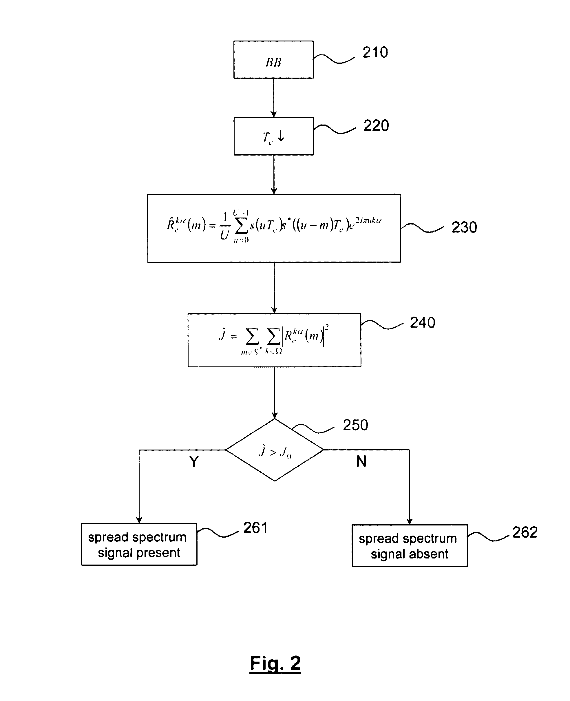
[0040]FIG. 2 illustrates the flowchart of a semi-blind method for detecting the presence of a s...

second embodiment

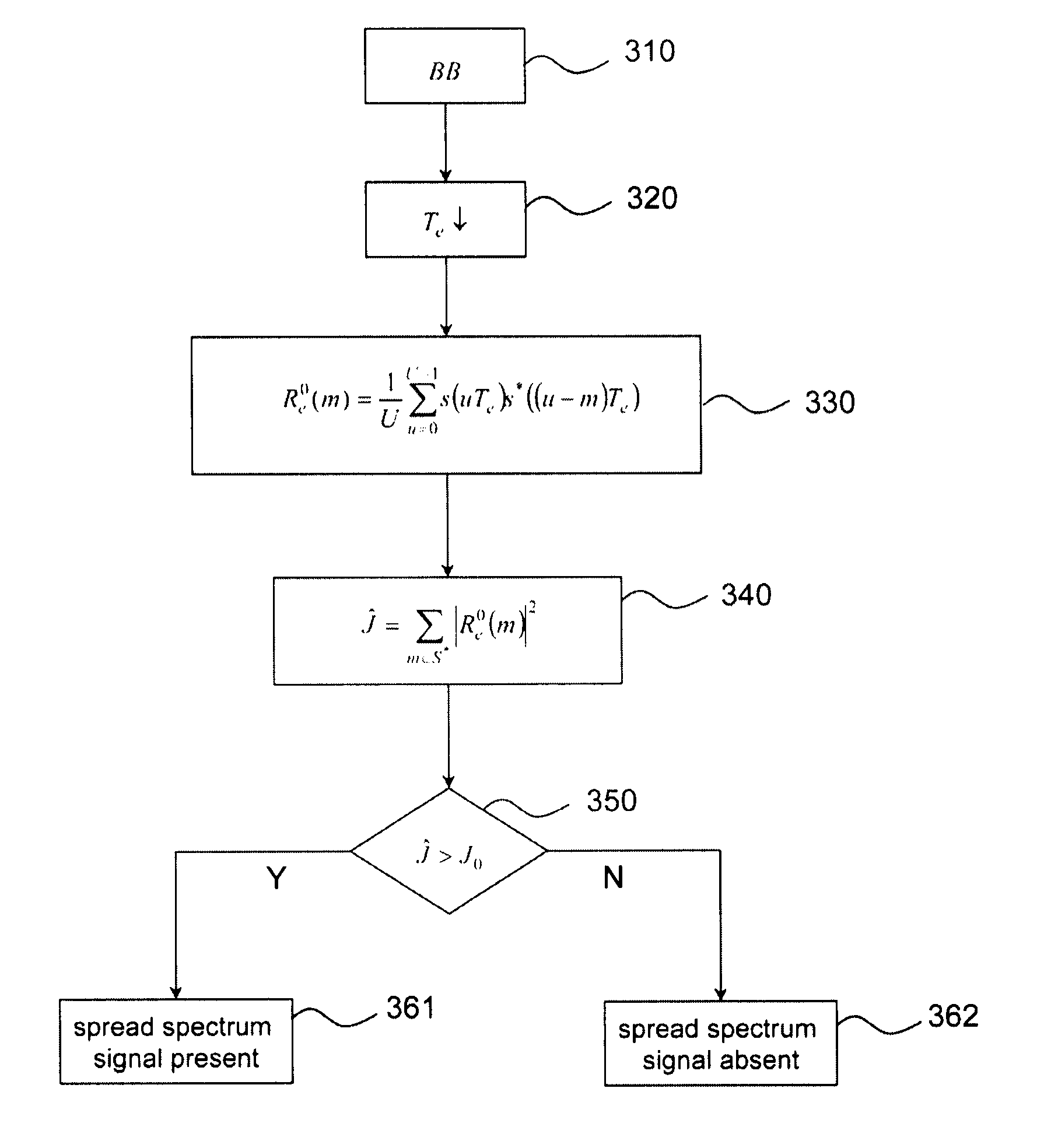
[0051]FIG. 3 illustrates the flowchart of a blind detection method for the presence of a spread spectrum signal in a spectral band of interest, according to the invention.

[0052]In step 310, the received signal is filtered in the band of interest and is translated into the base band.

[0053]In step 320, the obtained signal is sampled at the Nyquist frequency.

[0054]In 330, the cyclic correlation coefficient Re0(m) is estimated.

[0055]In 340, the energy of the autocorrelation function is estimated from expression (10). In practice, as for the first embodiment, the summation over the time shift values is limited to a bounded support S* which may have the same forms as earlier.

[0056]Eventually, the energy Ĵ is then obtained by:

J^=∑m∈S*1U∑u=0U-1s(uTe)s*((u-m)Te)2(13)

[0057]In 350, the value Ĵ is compared with a threshold value J0, determined as for the first embodiment (with card(Ω)=1) .

[0058]If Ĵ>J0, it is concluded in 361 that a spread spectrum signal is present in the band of interest, and...


PUM


Abstract

The present invention relates to a method for detecting the presence or the absence of a spread spectrum signal in a frequency band of interest of a received signal, wherein:the autocorrelation function of said received signal is calculated for a set (S*) of non-zero time shift values (m);at least one cyclic correlation coefficient on (Rekα(m)) of the autocorrelation function is determined for said time shift values;the energy of the autocorrelation function is estimated from the quadratic sum of the values assumed by said cyclic correlation coefficient for said time shift values;the thereby estimated energy is compared with a predetermined threshold value and the presence or absence of said spread spectrum signal in the received signal is inferred from the result of the comparison.

Description

TECHNICAL FIELD[0001]The present invention relates to the field of blind or semi-blind detection of spread spectrum signals. It notably finds application in cognitive radio systems.STATE OF THE PRIOR ART[0002]The increasingly large congestion of the spectrum has led to the consideration of telecommunications systems capable of coexisting with systems having already allocated frequency bands, so-called primary systems. Two coexistent strategies are presently the subject of significant research. The first consists of using a very low signal level by very strongly spreading out the spectrum, this is the way followed by ultra wide band systems further called UWB (Ultra Wide Band). The second consists of opportunistically using a portion of the spectrum which is punctually or temporarily unoccupied, this is the so-called opportunistic radio (or Cognitive Radio) way. A description of cognitive radio will be found in the founding thesis of J. Mitola entitled <<Cognitive radio: an int...

Claims


Application Information

Patent Timeline
IPC IPC(8): H04B1/69
CPCH04L27/0012
Inventor JALLON, PIERRE
Owner COMMISSARIAT A LENERGIE ATOMIQUE ET AUX ENERGIES ALTERNATIVES
Learn More