Moving image processing device, moving image processing method and imaging apparatus

a processing device and moving image technology, applied in signal generators with optical-mechanical scanning, color televisions with bandwidth reduction, signal generators, etc., can solve the problems of small improvement in image quality of face protection regions, significant degraded image quality of other regions, and meaningless quantization index correction from qsub, etc., to achieve sufficient compression ratio of small-area face regions (specific targets), small compression ratio of specific target regions, and large compression ratio reduction

Active Publication Date: 2010-07-29
PANASONIC CORP
View PDF3 Cites 26 Cited by
  • Summary
  • Abstract
  • Description
  • Claims
  • Application Information

AI Technical Summary

Benefits of technology

[0019]In the present invention, the degree of reduction in the compression ratio of the specific target region is small in the case where the ratio of the area of the specific target region (typically, a face region) to the entire area of the input image is relatively large. On the other hand, the degree of reduction in the compression ratio of the specific target region is large in the case where the ratio of the area of the specific target region to the entire area of the input image is relatively small. With this configuration, even if the va...

Problems solved by technology

An increase in the reference quantization index Q0 itself, however, makes it meaningless to correct the quantization index from Q0 to Q0−3 by using the face detection info...

Method used


Image

  • Moving image processing device, moving image processing method and imaging apparatus
  • Moving image processing device, moving image processing method and imaging apparatus
  • Moving image processing device, moving image processing method and imaging apparatus

Examples


first embodiment

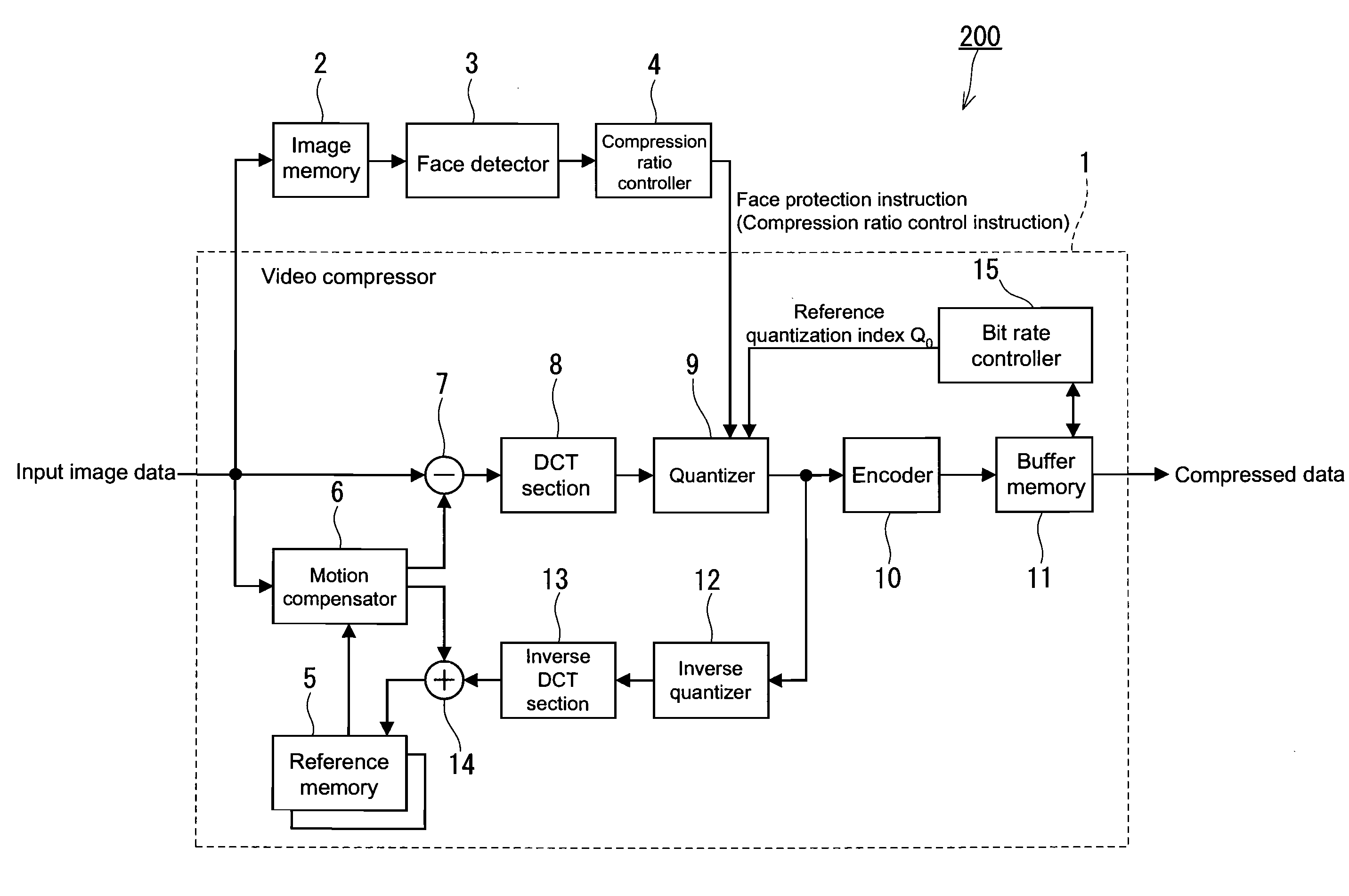
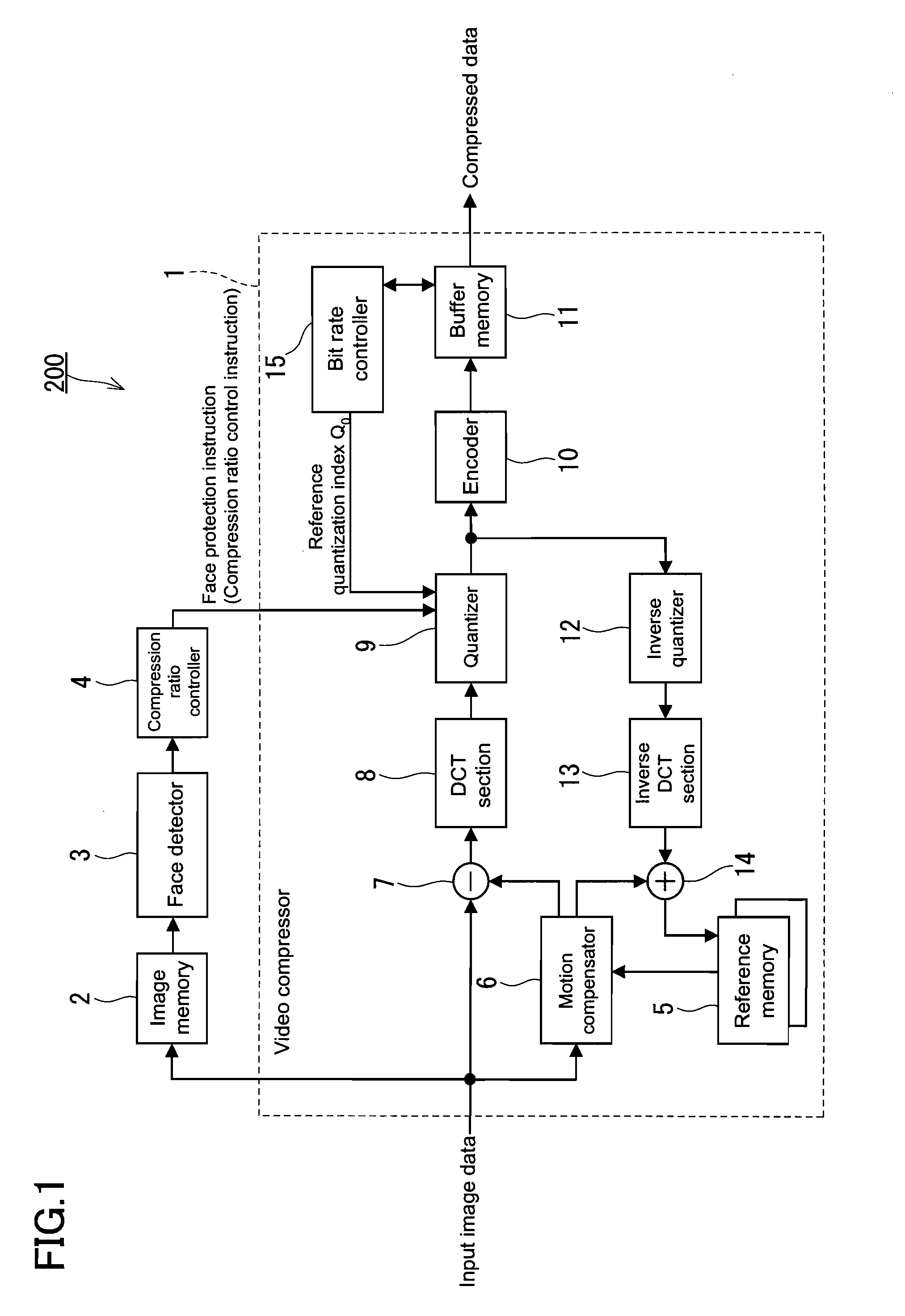
[0038]FIG. 1 is a block diagram showing a configuration of a moving image processing device according to a first embodiment of the present invention. FIG. 1 merely shows a typical configuration of a moving image processing device, and not all the components are essential.

[0039]As shown in FIG. 1, a moving image processing device 200 includes a video compressor 1, an image memory 2, a face detector 3, and a compression ratio controller 4. Input image data is supplied to the video compressor 1 and the image memory 2 respectively, and the output of the image memory 2 is supplied to the face detector 3. The face detector 3 detects (extracts), as a specific target, a face in the input image data, and outputs face detection information. The compression ratio controller 4 generates a face protection instruction based on the face detection information obtained from the face detector 3, and outputs the generated instruction. The “face protection instruction” means a compression control instr...

second embodiment

[0078]The configuration of a moving image processing device in the second embodiment of the present invention is the same as that in the first embodiment of the present invention. The only difference in the operation of the device in the second embodiment is the processing performed by the compression ratio controller 4.

[0079]The operation of the device in the second embodiment is described below with a focus on that difference.

[0080]The compression ratio controller 4 receives face detection information from the face detector 3 at the time indicated by the character C in FIG. 6, and identifies the face protection region in the same manner as in the first embodiment of the present invention. FIG. 10 shows a relationship between an input image and a plurality of face protection regions that are different from each other in size. The compression ratio controller 4 identifies the face protection region of the face A and that of the face B, and calculates individually the areas of these ...


PUM


Abstract

A moving image processing device (200) includes a face detector (3) (specific target detector), a compression ratio controller (4), and a quantizer (9) (video compressor). The face detector (3) detects a person's face included in an input image and extracts a face region. The compression ratio controller (4) generates and outputs a compression control instruction for reducing the compression ratio of the face region extracted by the face detector (3) so that a degree of reduction in the compression ratio of the face region is small in the case where the ratio of the area of the face region to the entire area of the input image is relatively large and so that the degree of reduction in the compression ratio of the face region large in the case where the ratio of the area of the face region to the entire area of the input image is relatively small. The quantizer (9) performs a quantization processing of the face region according to the compression control instruction given from the compression ratio controller (4).

Description

BACKGROUND OF THE INVENTION[0001]1. Field of the Invention[0002]The present invention relates to a moving image processing device for compressing video images.[0003]2. Description of Related Art[0004]In recent years, highly efficient video compression techniques, such as MPEG-2 (ITU-T H.262) and H.264 / MPEG-4 AVC standards, have made significant progress. These video compression techniques are used in the field of video cameras and recorders. In these fields, various techniques have been developed to achieve better image quality at lower bit rates. In these techniques, a low compression ratio is set for a viewer's attention region in an input image to improve the image quality while a higher compression ratio is set for the other region to reduce the bit rate. Various ways to compress images while protecting the portion of a person's face in particular as an attention region have been studied and proposed actively. In these techniques, a person's face is detected based on its charact...

Claims


Application Information

Patent Timeline
IPC IPC(8): H04N7/12H04N19/60H04N19/126H04N19/167H04N19/176H04N19/189H04N19/20H04N19/423H04N19/503H04N19/51H04N19/61H04N19/625H04N19/91
CPCH04N19/126H04N19/17H04N19/152
Inventor FUJII, SYOUZOUOKA, HIDEMI
Owner PANASONIC CORP
Why Eureka
Try Eureka