Mirror unit and image capturing apparatus

a technology of mirror unit and image capturing apparatus, which is applied in the direction of mountings, instruments, and exposure control, can solve the problem of delayed initiation of distance measuremen

Inactive Publication Date: 2010-07-29
NIKON CORP
View PDF1 Cites 17 Cited by
  • Summary
  • Abstract
  • Description
  • Claims
  • Application Information

AI Technical Summary

Benefits of technology

[0007]To solve this problem, a first aspect of the present invention provides a mirror unit comprising a first mirror (102) that reflects and passes incident light from a subject side; a second mirror (104) that reflects the incident light passed by the first mirror; a first mirror holder (110) that holds the first mirror, is rotatable on a rotational axis arranged above an optical path of the incident light, is lowered to a first mirror-down position in which the first mirror is inserted into the optical path of the incident light, and is raised to a first mirror-up position in which the first mirror is removed from the optical path of the incident light; and a second mirror holder that includes an auxiliary component (114) and a mirror holding compone...

Problems solved by technology

In other words, initiation of distance measuremen...

Method used


Image

  • Mirror unit and image capturing apparatus
  • Mirror unit and image capturing apparatus
  • Mirror unit and image capturing apparatus

Examples


Embodiment Construction

[0029]Hereinafter, some embodiments of the present invention will be described. The embodiments do not limit the invention according to the claims, and all the combinations of the features described in the embodiments are not necessarily essential to means provided by aspects of the invention.

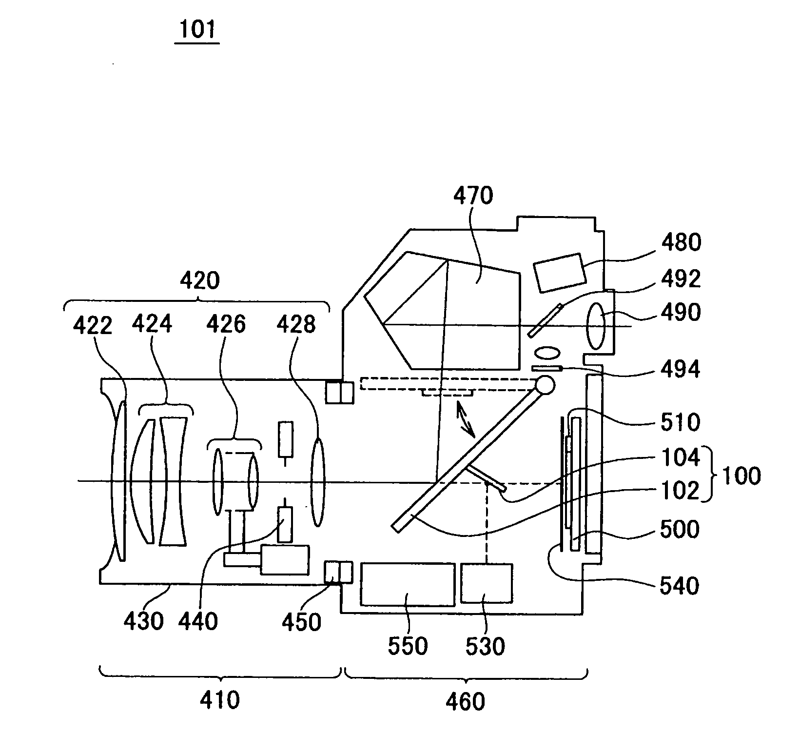
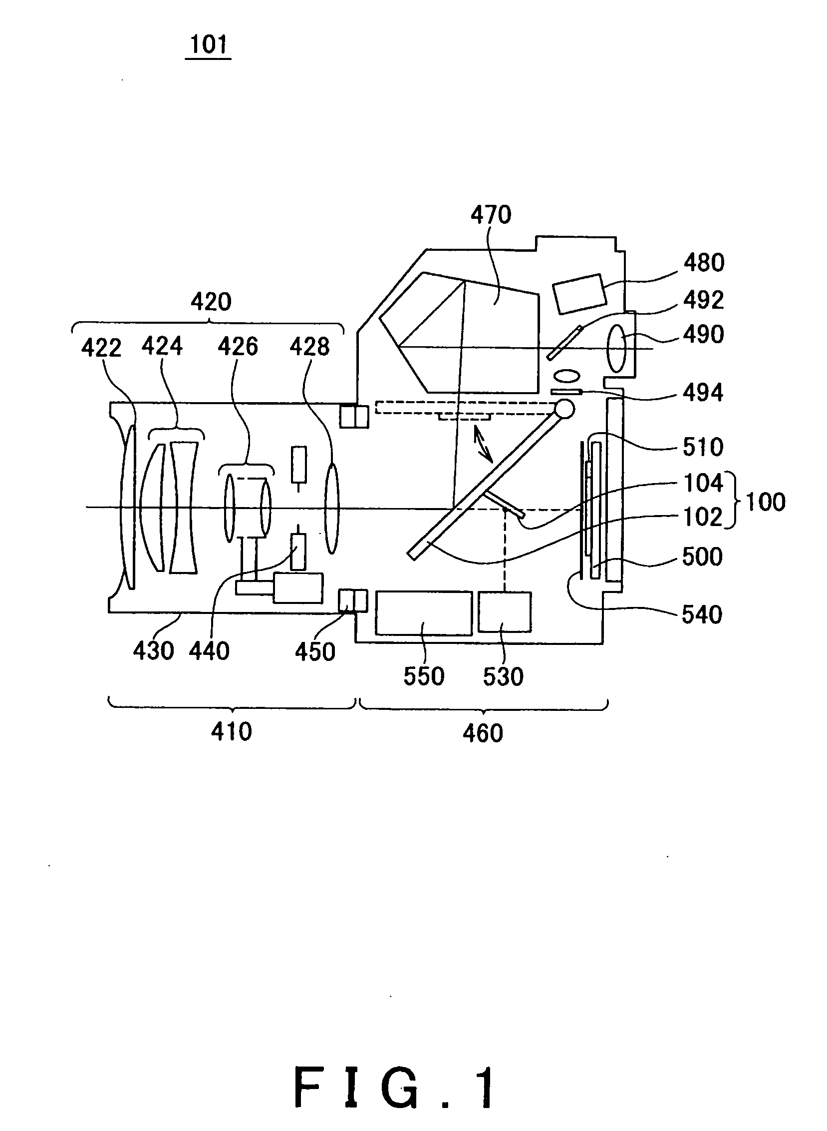
[0030]FIG. 1 is a schematic cross-sectional side view of a single lens reflex digital camera 101 provided with a mirror unit 100 according to an embodiment of the present invention. As shown in FIG. 1, the digital camera 101 is provided with an optical component 420, a lens barrel 430, an image capturing unit 500 such as a CCD, and a control section 550. The lens barrel 430 houses the optical component 420. The image capturing unit 500 captures an image of a subject that is focused by the optical component 420. The control section 550 controls the image capturing unit 500.

[0031]The digital camera 101 includes a lens unit 410, which contains the optical component 420 and the lens barrel 430, and...


PUM


Abstract

Goal: Providing a mirror unit that can decrease the wait time before distance measurement.
Means: A mirror unit comprising a first mirror; a second mirror; a first mirror holder that holds the first mirror, is rotatable on a rotational axis arranged above an optical path of the incident light, is lowered to a first mirror-down position, and is raised to a first mirror-up position; and a second mirror holder that includes an auxiliary component and a mirror holding component holding the second mirror, is lowered to a second mirror-down position, and is raised to a second mirror-up position, wherein the auxiliary component is provided below the first mirror holder in the direction of the lowering, is rotatable on a rotational axis that is the same as or parallel to the rotational axis of the first mirror holder, and can be lowered independently of the first mirror holder, and the mirror holding component is engaged with the auxiliary component to be relatively rotatable around a rotational axis that is parallel to the rotational axis of the auxiliary component.

Description

BACKGROUND[0001]1. Technical Field[0002]The present application claims priority from a Japanese Patent Application No. 2009-014052 filed on Jan. 26, 2009, the contents of which are incorporated herein by reference.[0003]The present invention relates to a mirror unit and an image capturing apparatus.[0004]2. Related Art[0005]A known mirror unit for a single lens reflex camera includes a main mirror, which is a half mirror, and a sub-mirror that reflects the light passed by the main mirror downward to a distance measuring sensor, and these mirrors are lowered into the optical path or raised above the optical path, as shown in Japanese Patent Application Publications No. 62-78536 and No. 63-95430. In such a mirror unit, a sub-frame holding the sub-mirror hangs down to be rotatable relative to a main frame holding the main mirror.[0006]To achieve accurate distance measurement, it is desirable that measurement be started after vibration of the lowered sub-mirror has stopped. However, in ...

Claims


Application Information

Patent Timeline
IPC IPC(8): G03B13/00G02B7/182
CPCG03B13/00
Inventor KURAHASHI, TOSHIAKI
Owner NIKON CORP
Why Eureka
Try Eureka