Self-Clearing Self-Cutting Implant

a self-clearing, dental implant technology, applied in the field of bone implants, can solve the problems of inability to effectively clear bone chips from holes, limited thread cutting abilities of present devices, and poor self-clearing devices of prior art, so as to improve self-clearing implants, reduce the torque for insertion, and increase the load bearing surface

Active Publication Date: 2010-07-29
INTRA LOCK INT
View PDF33 Cites 41 Cited by
  • Summary
  • Abstract
  • Description
  • Claims
  • Application Information

AI Technical Summary

Benefits of technology

[0025]It is an object of this invention to provide an improved self tapping implant having reduced torque for insertion and an increased load bearing surface at the time of insertion.

Problems solved by technology

Self tapping devices of the prior art suffer from a number of drawbacks.
The thread cutting abilities of present devices are limited due to the thickness of the threads which creates large amounts of bone chips as part of the cutting process.
Current designs are unable to effectively clear these bone chips from the hole.
This results in an increase in the torque required to seat a self tapping implant.
The increase in torque adds to patient discomfort and may also lead to breakage of the threads cut in the bone.
The inability of the implant to clear debris can also prevent a surgeon from properly seating an implant.
The seating and insertion torque problems increase as the length of the implant increases.
However, this is not a self tapping implant.

Method used


Image

  • Self-Clearing Self-Cutting Implant
  • Self-Clearing Self-Cutting Implant
  • Self-Clearing Self-Cutting Implant

Examples


Embodiment Construction

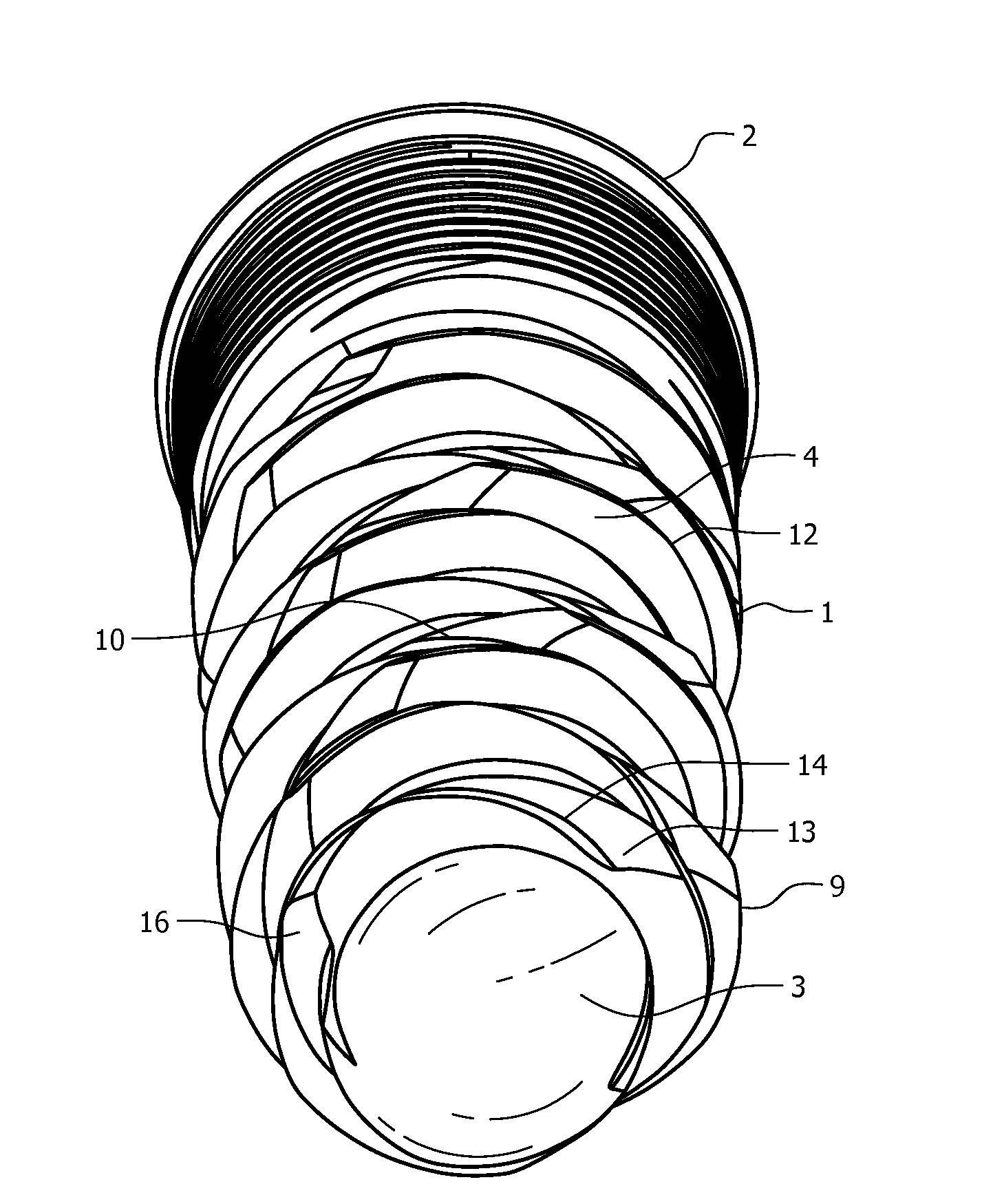
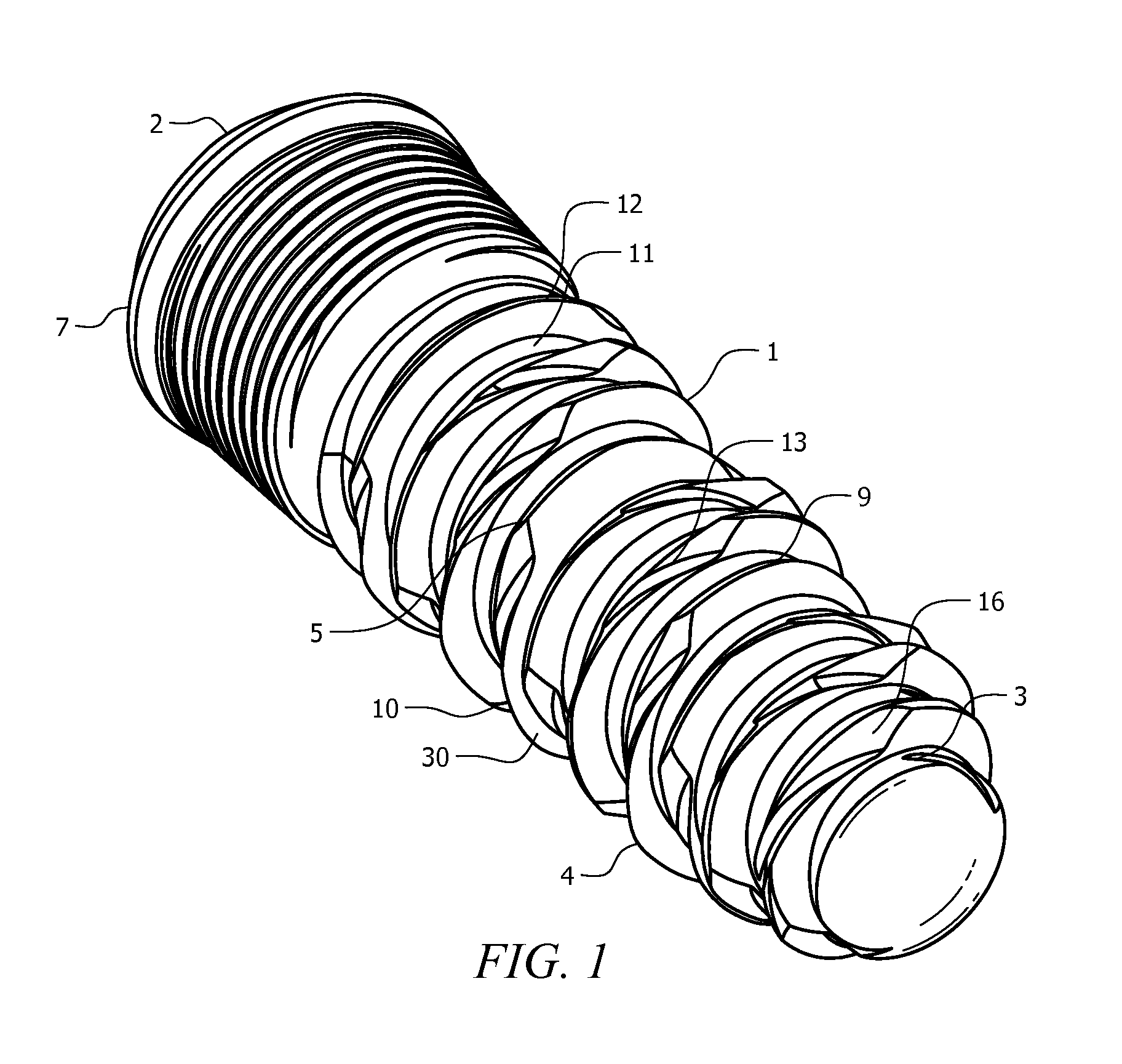
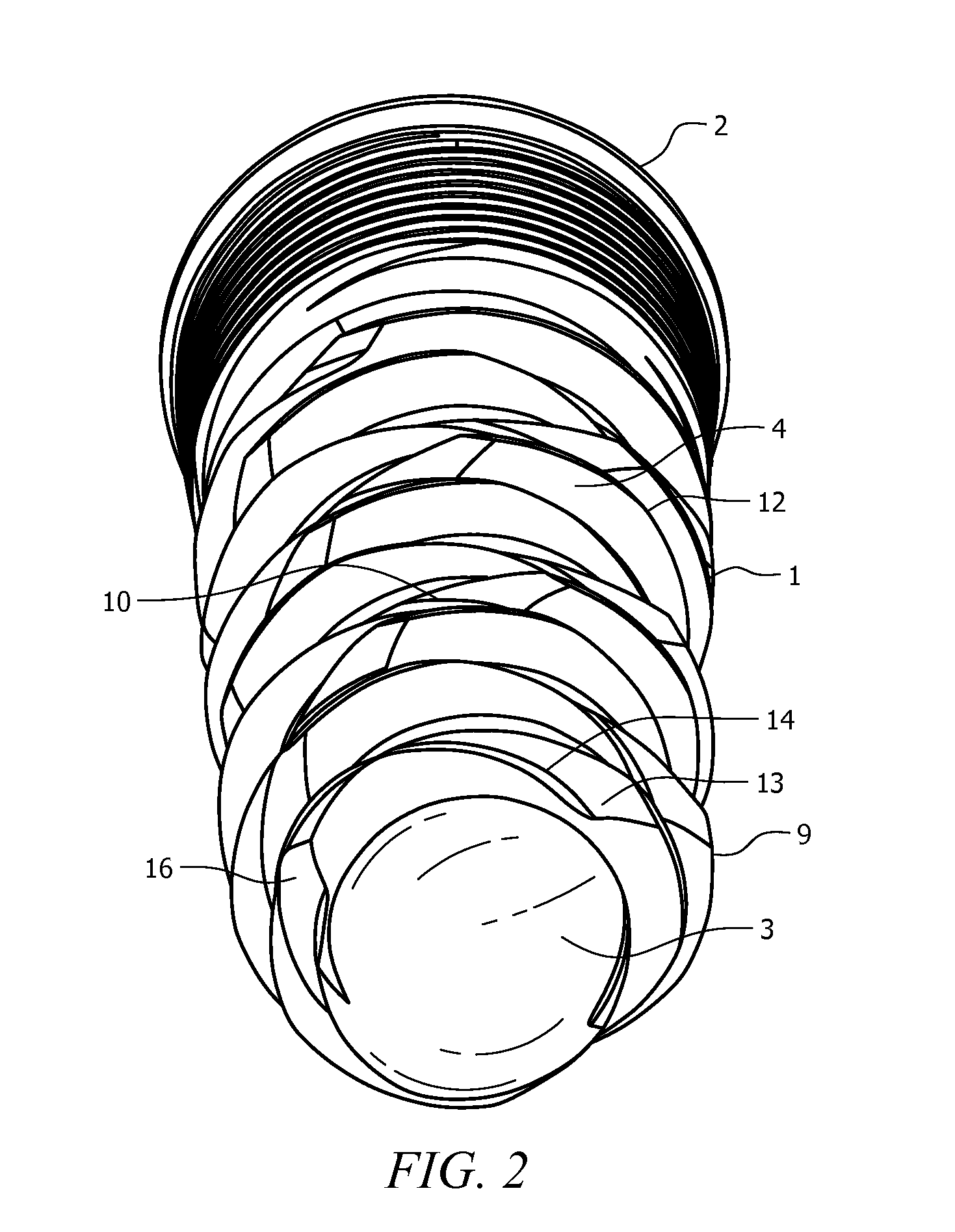
[0037]The present invention comprises a self tapping implant which requires substantially less torque to install than devices currently in use. The reduction in effort is achieved by the inclusion of at least one cutting surface on each rotation of the thread and by including a spiral groove which runs in an opposite direction to the threads. This enables the implant of the present invention to corkscrew into an opening instead of cutting course threads.

[0038]Referring to FIGS. 1-3, according to one dental implant embodiment, the implant comprises a substantially cylindrical body 1 having a proximal end 2 and a distal end 3. The proximal end contains a prosthetic platform 7 onto which a prosthesis will be fitted. The body contains at least one external helical thread 9 which runs from the distal end 3 to the proximal end 2. The helical thread 9 maybe right or left handed and contains at least one cutting edge 6 for each turn of the cutting head. The implant further comprises a secon...


PUM


Abstract

The invention relates to bone implants, namely screw-type implants and, more particularly, to a self tapping dental implant having at least two helical grooves running in opposite directions around the implant.

Description

[0001]This application claims priority to provisional application Ser. No. 61 / 147,630 filed on Jan. 27, 2009, the contents of which are expressly incorporated herein by reference.FIELD OF INVENTION[0002]The invention relates to bone implants, namely screw-type implants and, more particularly, to a self tapping dental implant having at least two helical grooves running in opposite directions around the implant.BACKGROUND OF THE INVENTION[0003]Implants for insertion into living bone, including screw type implants are widely used and are well known in the art. Such implants may be used in dentistry or orthopedics. The screw tapping implants generally fall into the category of self-tapping implants and non-self tapping implants. Non-self tapping implants are merely threaded and are screwed into the bone after it is separately drilled and tapped. Self tapping implants contain cutting threads analogous to those in a metal tap which cut threads into the bone when inserted in a drilled hole...

Claims


Application Information

Patent Timeline
Patent Type & Authority Applications(United States)
IPC IPC(8): A61C8/00A61B17/86
CPCA61B17/8605A61C8/0022A61B17/863
Inventor GIORNO, THIERRY
Owner INTRA LOCK INT
Why Eureka
Try Eureka