Cannulated apparatus and method relating to microfracture and revascularization methodologies

a microfracture and cannula technology, applied in the field of cannulated microfracture apparatus, can solve the problems of uneven formation of one or a plurality of holes, uneven drilling, uneven penetration depth, etc., and achieve the effect of simple addition of bone penetration and speeding patient recovery

Inactive Publication Date: 2010-07-29
KIRSCHENBAUM IRA
View PDF8 Cites 43 Cited by
  • Summary
  • Abstract
  • Description
  • Claims
  • Application Information

AI Technical Summary

Benefits of technology

[0018]Another aspect of the present invention is to provide a cannulated microfracture kit that allows a regulated application of microfracture force and comprehensive control of microfracture location.
[0030]According to another aspect of the present invention, there is provided a kit including a depth-of-penetration-stop mechanism enabling a user-surgeon to regulate pick-penetration within a force range, thereby improving a regulation of penetration during use.

Problems solved by technology

The employment of debridement burrs, smooth pins, and drilling has fallen out of favor due to the consequential heat necrosis or cell death brought on by in situ heat buildup.
Unfortunately, due to simple human error the resultant force drives the generally conical tip into the target bone at an angle other than axial to the point itself often damaging the bone and the preferably-reached subchrondral bone, forming one or a plurality of non-uniform holes.
Such holes are generally arrayed in an undesirably interfering and irregular or overlapping mosaic fashion based upon the inaccuracy of physical-directed positioning (leading to improper angle, penetration depth, and force use errors).
Unfortunately, a number of detriments have not been appreciated by the prior art, namely resulting from employing the current microfracture pick techniques.
These detriments include:(a) The further a user drives the pick into the bone uncontrollably resulting in a wider-than-optimal part of the resultant hole.(b) Substantially all of the pick angles at the end of each pick-tool shaft do not drive well or cleanly (meaning linearly to a pick-tip-axis with the application of force along a pick-tip axis).(c) The surgeon is often unable to apply sufficient, regular, or uniform force to drive the pick consistently deeply enough to effect a desired medical outcome—resulting in unsuccessful re-vascularation locations.(d) A surgeon is unable to reliably and repeatedly reposition the pick relative to the desired bone target following successive uses, thereby resulting in scattered, inaccurate and potentially damaging hole placement and a general difficulty in creating a uniform mosaic pattern for revascularization.

Method used


Image

  • Cannulated apparatus and method relating to microfracture and revascularization methodologies
  • Cannulated apparatus and method relating to microfracture and revascularization methodologies
  • Cannulated apparatus and method relating to microfracture and revascularization methodologies

Examples


Embodiment Construction

[0092]Reference will now be made in detail to several embodiments of the invention that are illustrated in the accompanying drawings. Wherever possible, same or similar reference numerals are used in the drawings and the description to refer to the same or like parts or steps. The drawings are in simplified form and are not to precise scale. For purposes of convenience and clarity only, directional terms, such as top, bottom, up, down, over, above, and below may be used with respect to the drawings. These and similar directional terms should not be construed to limit the scope of the invention in any manner. The words “connect,”“couple,” and similar terms with their inflectional morphemes do not necessarily denote direct and immediate connections, but also include connections through mediate elements or devices.

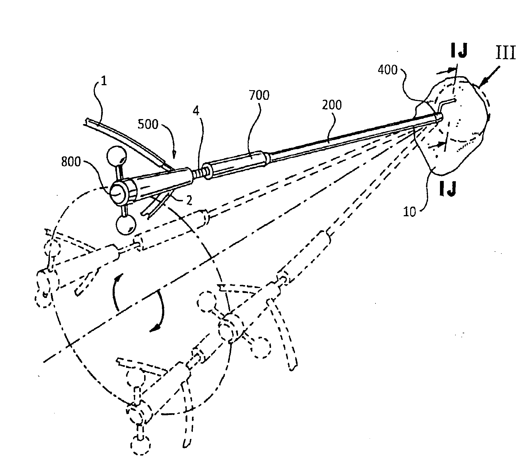
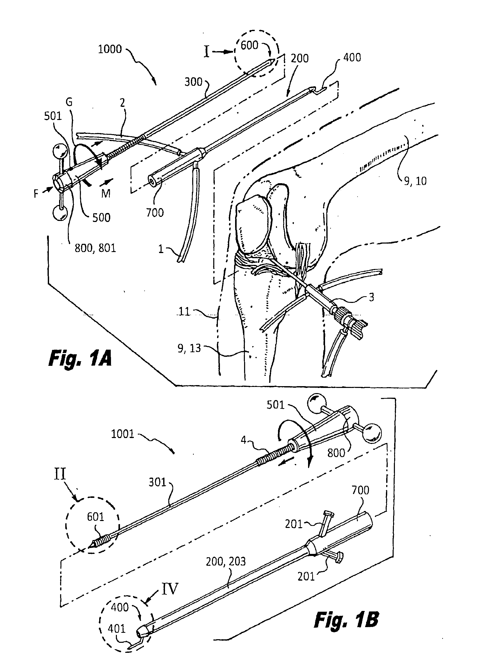
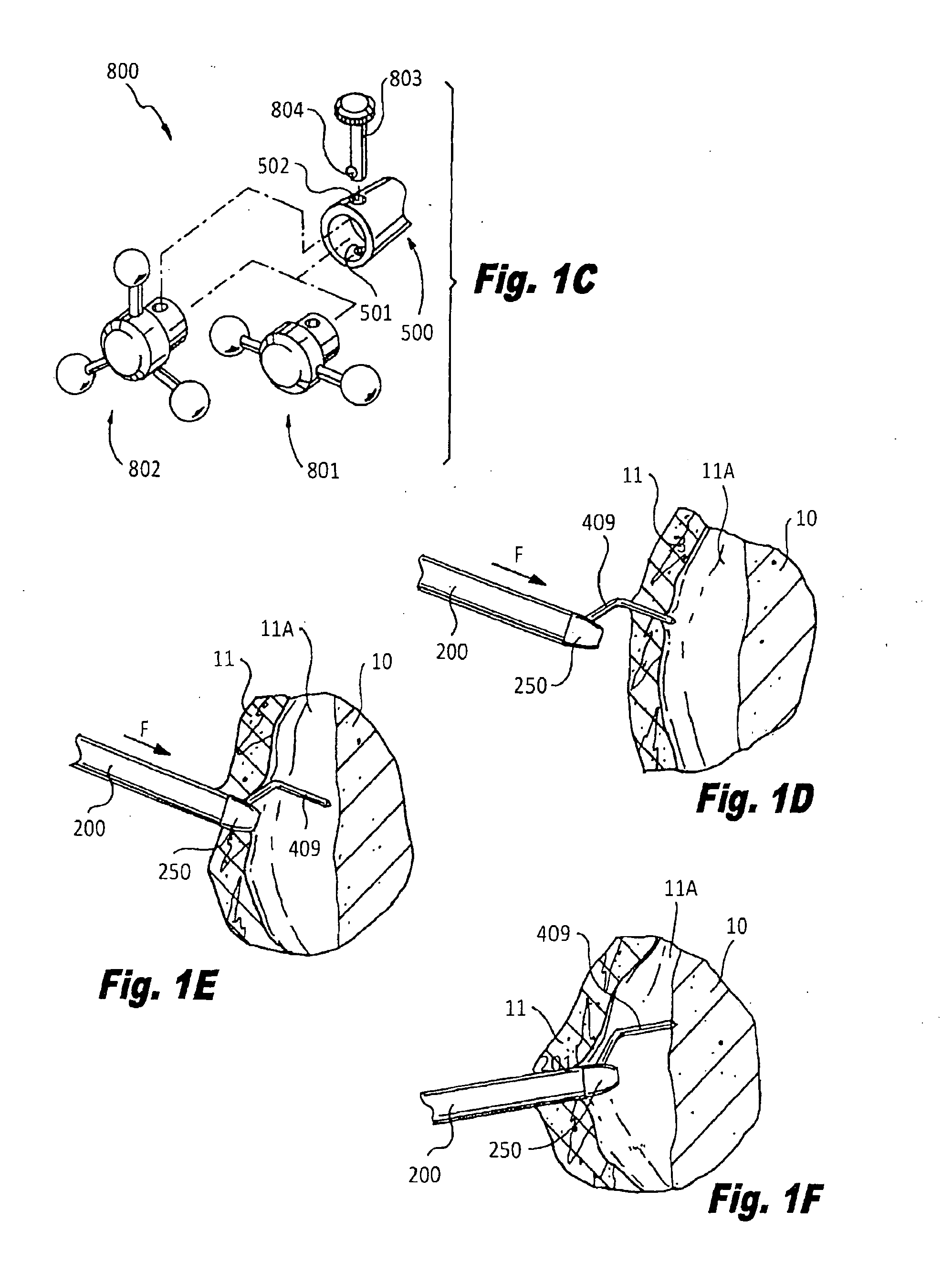
[0093]Referring now to FIGS. 1A-1C, a first and second cannulated microfracture system 1000, 1001 each include respectively a trocar 300, 301 having respective contact tip en...


PUM


Abstract

The present invention relates to a carrnulated microfracture kit, apparatus, and method for using the same during a medical treatment. The present kit enables precise and repeated positioning, the regulation and repetition of microfracture force application, and a control of a mosaic bone penetration and other surgical control improvement features. The present invention overcomes the detriments resultant from prior techniques in an apparatus that is readily adaptable to a variety of adaptive orthopedic surgical procedures. Assembled and selectable kits are provided.

Description

CROSS REFERENCE TO RELATED APPLICATION[0001]This application claims priority to U.S. Provisional Application Ser. No. 60 / 828,654 filed Oct. 8, 2006, the entire contents of which are herein incorporated by reference.BACKGROUND OF THE INVENTION[0002]1. Field of the Invention[0003]The present invention relates to a cannulated microfracture apparatus and methods for implementing the same. More specifically, the present invention relates to a cannulated delivery apparatus functionally employing a microfracture device and a method for operating the same to augment revascularization.[0004]2. Description of the Related Art[0005]Within the broad field of orthopeadic (orthopedic) surgery, various physical techniques and methods have been developed to aid revascularization of arthritic or otherwise damaged or necrotic bone; principally in localities proximate knee, hip, and ankle joints, although there is no limitation to these revascularization regions.[0006]Previously employed methods includ...

Claims


Application Information

Patent Timeline
Patent Type & Authority Applications(United States)
IPC IPC(8): A61M5/32
CPCA61B17/1604A61B17/1644A61B17/1657A61B2217/007A61B17/1735A61B2217/005A61B17/1675
Inventor KIRSCHENBAUM, IRA
Owner KIRSCHENBAUM IRA
Why Eureka
Try Eureka