
System and Method for Refractive Surgery with Augmentation by Intrastromal Corrective Procedures

a technology of corrective procedures and laser surgery, applied in laser surgery, medical science, surgery, etc., can solve the problems of limiting the extent of effective refractive correction, neither the removal of corneal tissue, nor the and unable to achieve the desired refractive effect, and achieve the effect of greater weakening of stromal tissu

Active Publication Date: 2010-07-29
TECHNOLAS PERFECT VISION
View PDF30 Cites 17 Cited by
  • Summary
  • Abstract
  • Description
  • Claims
  • Application Information

AI Technical Summary

Benefits of technology

[0007]A system and method are provided for performing an ophthalmic laser surgical procedure, wherein a required (desired) refractive correction for an eye necessitates removal of more corneal tissue than can be efficaciously removed by photoablation alone. It follows that the required refractive correction also necessitates a greater weakening of stromal tissue than is possible by LIOB alone. The present invention, however, recognizes that the removal of an optimal amount of corneal tissue, by ablation, can be complemented by a weakening of stromal tissue, by LIOB, to achieve a required overall refractive correction for an eye.

Problems solved by technology

It can happen, however, that neither the removal of corneal tissue, nor the weakening of stromal tissue, when performed alone, may be able to achieve the desired refractive result.
Thus, there are limits to the extent of an effective refractive correction when either a weakening of stromal tissue or an actual removal of tissue are considered separately.
The inherent limitations of tissue removal procedures are primarily a result of the amount of corneal tissue that can be removed.
Specifically, for the rather common visual defects of myopia, hyperopia and astigmatism, it is known that going beyond the limits set forth below can cause unwanted instabilities in the cornea.
In general, the practical limits for effective refractive corrections to be achieved for the more common visual defects, by tissue removal alone, are:

Method used


Image

  • System and Method for Refractive Surgery with Augmentation by Intrastromal Corrective Procedures
  • System and Method for Refractive Surgery with Augmentation by Intrastromal Corrective Procedures
  • System and Method for Refractive Surgery with Augmentation by Intrastromal Corrective Procedures

Examples


Embodiment Construction

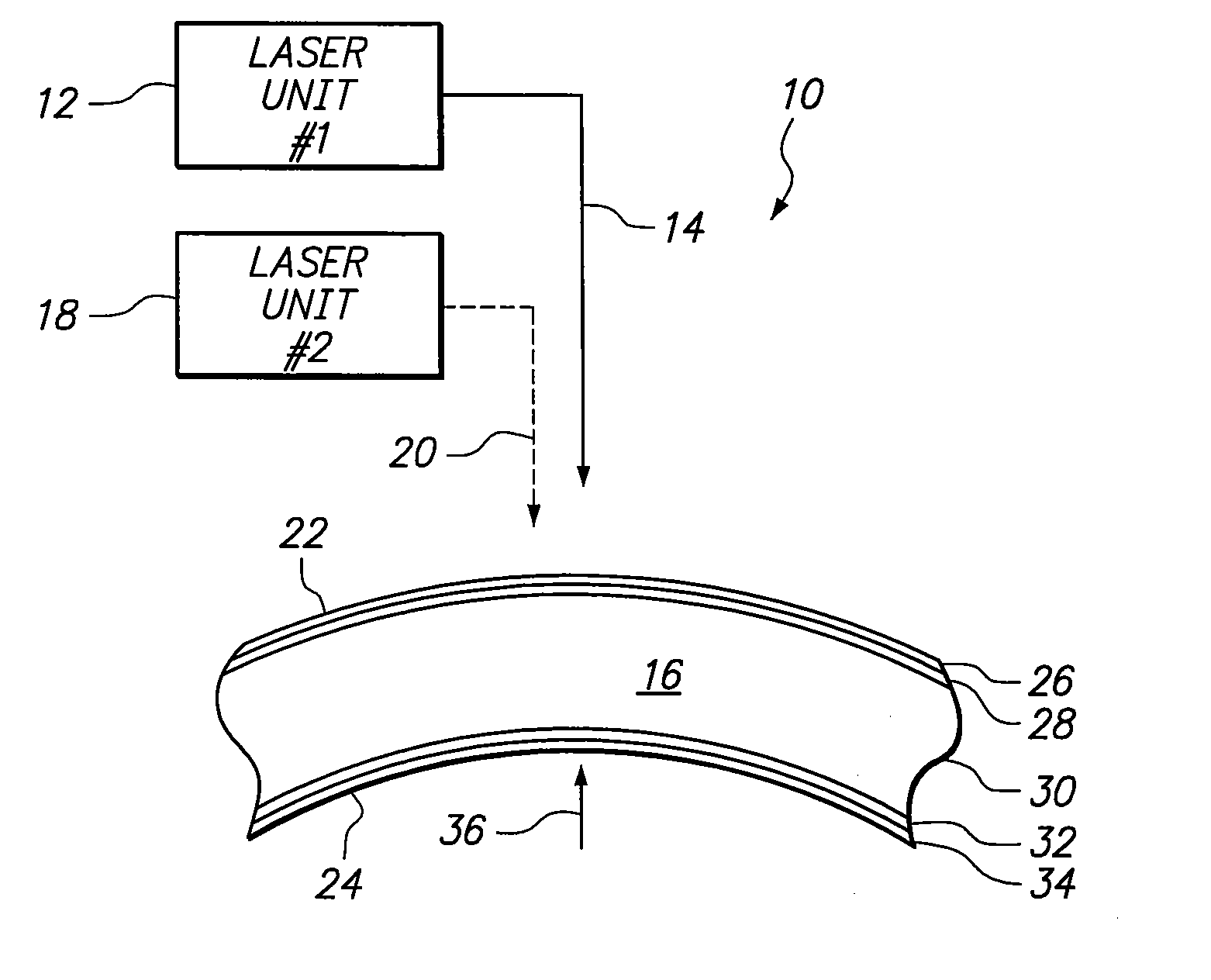
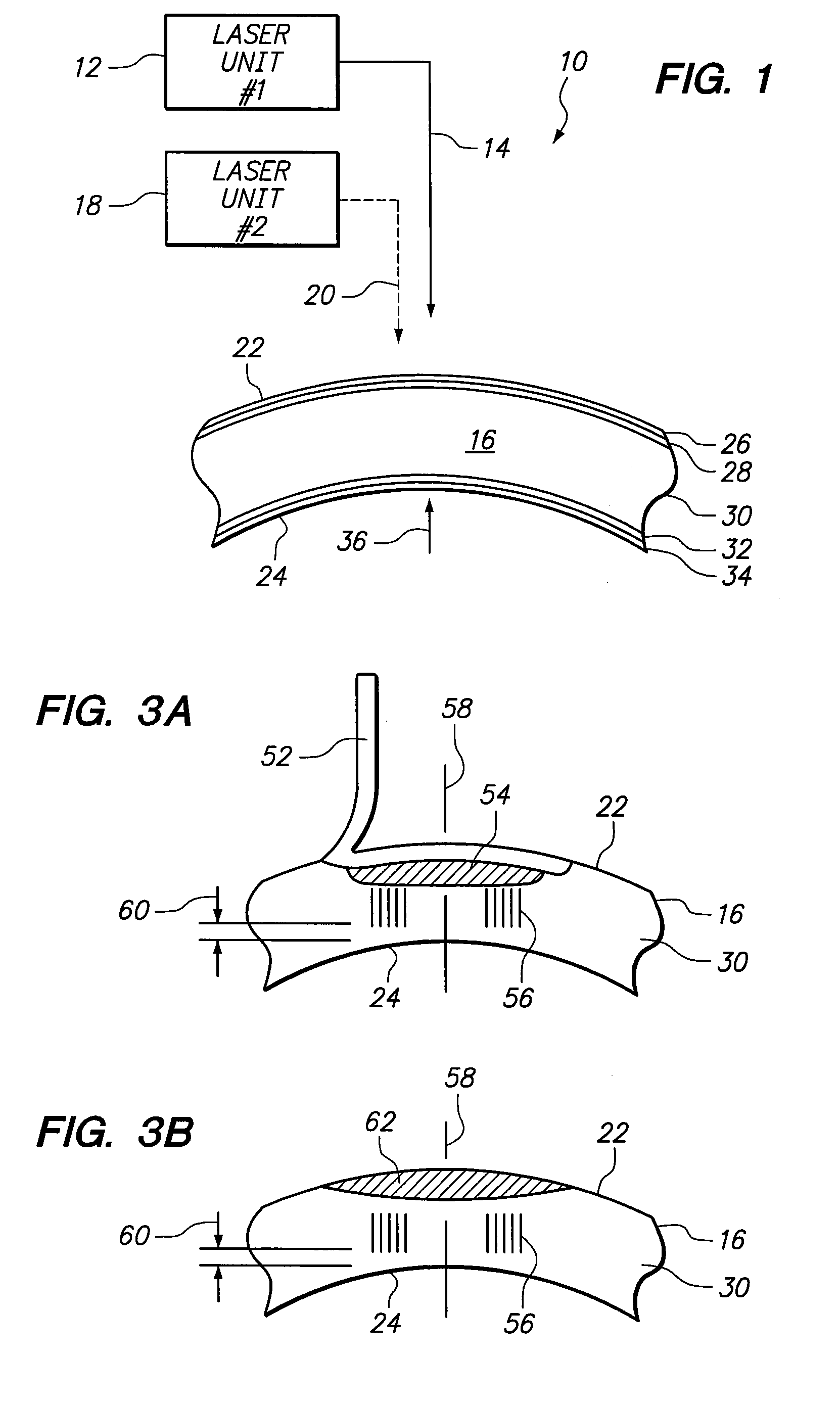
[0016]Referring initially to FIG. 1 a system for use with the present invention is shown and is generally designated 10. As shown, the system 10 includes a first laser unit 12 for generating and directing a laser beam along a beam path 14 toward the cornea 16 of an eye. The system 10 also includes a second laser unit 18 for generating and directing a laser beam along a beam path 20 toward the cornea 16. For purposes of the present invention, the first laser unit 12 is of a type well known in the pertinent art that is capable of generating a laser beam for photoablating tissue of the cornea 16, such as an excimer laser. On the other hand, the second laser unit 18 is of a type that is better suited to cause the Laser Induced Optical Breakdown (LIOB) of tissue in the cornea 16. Thus, the second laser unit 18 is preferably of a type that will generate a so-called, pulsed femtosecond laser beam.

[0017]Anatomically, the cornea 16 of an eye is shown in FIG. 1 to include, in order from its a...


PUM


Abstract

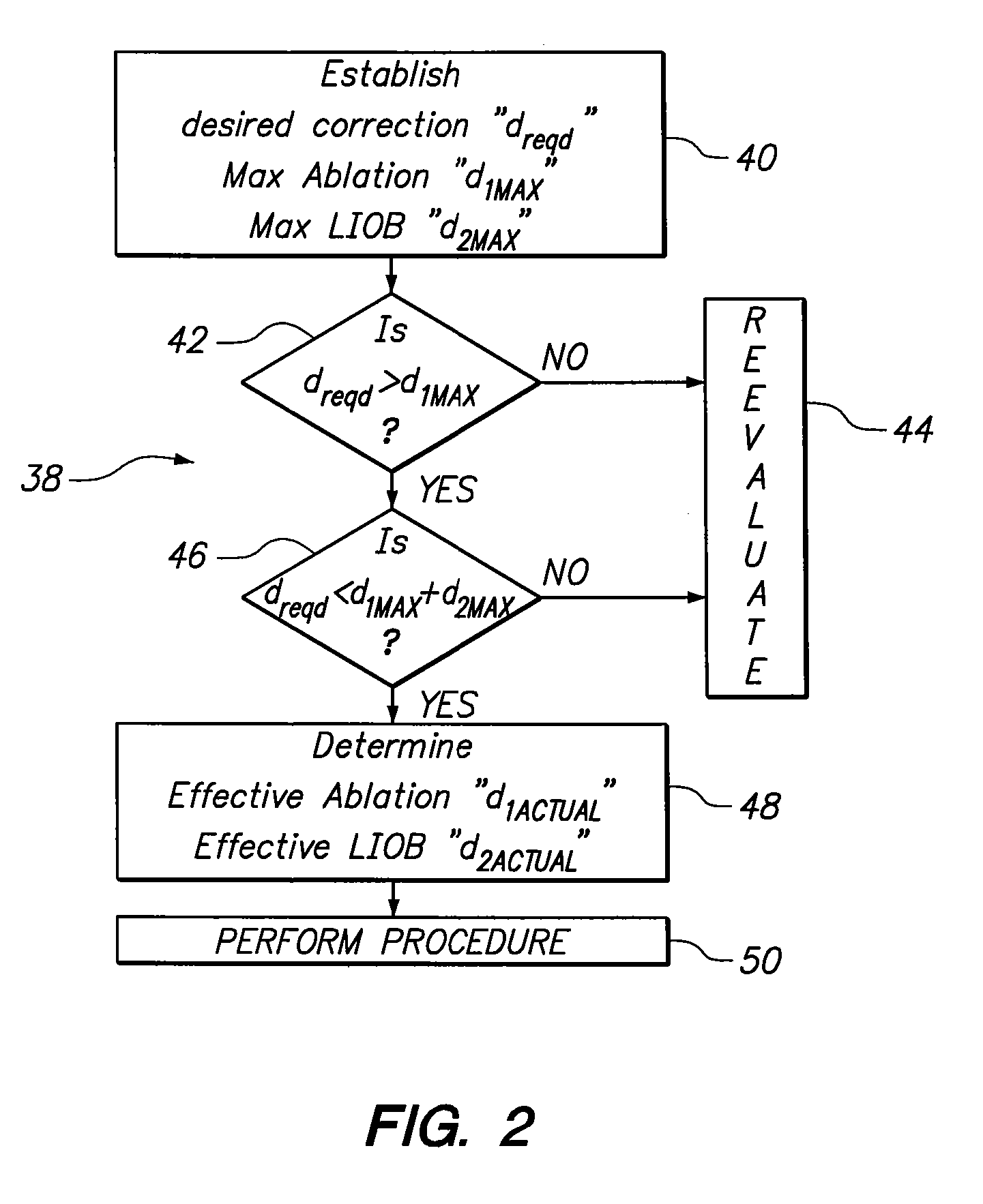
A system and method are provided for an ophthalmic surgical procedure to provide a refractive correction for an eye. Specifically, the procedure is indicated when the desired refractive correction “dreqd” exceeds the capability of a correction achievable when corneal tissue is only ablated. In accordance with the present invention, an optimized refractive correction “d1” is accomplished by the ablation of corneal tissue (e.g. by a PRK or LASIK procedure). The optimized correction is then followed by a complementary refractive correction “d2” wherein stromal tissue is weakened with Laser Induced Optical Breakdown (LIOB). Together, the optimized refractive correction (ablation) and the complementary refractive correction (LIOB) equal the desire refractive correction (dreqd=d1+d2).

Description

FIELD OF THE INVENTION[0001]The present invention pertains to systems and methods for ophthalmic laser surgical procedures. More particularly, the present invention pertains to laser surgery wherein a desired refractive correction requires removal of more corneal tissue than can be efficaciously removed by a single procedure. The present invention is particularly, but not exclusively, useful for surgery wherein a removal of corneal tissue by ablation is complemented by a weakening of stromal tissue by Laser Induced Optical Breakdown (LIOB) to collectively achieve a required refractive correction for an eye.BACKGROUND OF THE INVENTION[0002]Presently there are several different types of procedures that can be used for performing refractive surgery on the cornea of an eye to correct vision defects. In general, these procedures can be categorized according to the kind of instrument that is used to perform the surgery (e.g. a “mechanical means” or a “laser means”). Further, within the “l...

Claims


Application Information

Patent Timeline
Patent Type & Authority Applications(United States)
IPC IPC(8): A61F9/008A61B18/20
CPCA61F9/008A61F9/00804A61F2009/00872A61F2009/00857A61F9/00827
Inventor RUIZ, LUIS ANTONIOLOESEL, FRIEDERBILLE, JOSEF F.
Owner TECHNOLAS PERFECT VISION
Learn More