
Rod shearing instrument used in spinal surgical incision

A technology of surgical incision and scissors, which is applied in the field of medical appliances, can solve the problems of time-consuming and labor-intensive cutting process, and achieve the effect of avoiding the trouble of cutting and convenient operation

Pending Publication Date: 2022-03-15
杭州知橙生物科技有限公司
View PDF0 Cites 0 Cited by
  • Summary
  • Abstract
  • Description
  • Claims
  • Application Information

AI Technical Summary

Problems solved by technology

[0003] The present invention provides a scissors instrument for use in spinal surgery incisions, which has the advantages of saving time and effort, reducing risks, and cutting accurately, and solves the need to use cutting tools due to the limitations of scoliosis correction surgery. The fixing rod is removed for cutting, which leads to time-consuming and labor-intensive cutting process, as well as the risk of surgery

Method used


Image

  • Rod shearing instrument used in spinal surgical incision
  • Rod shearing instrument used in spinal surgical incision
  • Rod shearing instrument used in spinal surgical incision

Examples


Embodiment Construction

[0022] The following will clearly and completely describe the technical solutions in the embodiments of the present invention with reference to the drawings in the embodiments of the present invention.

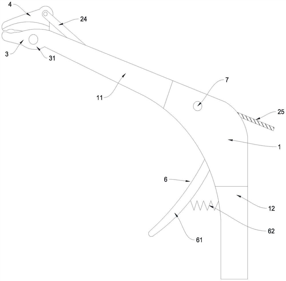
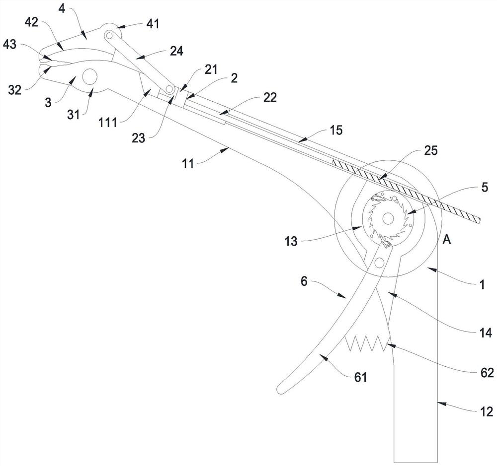
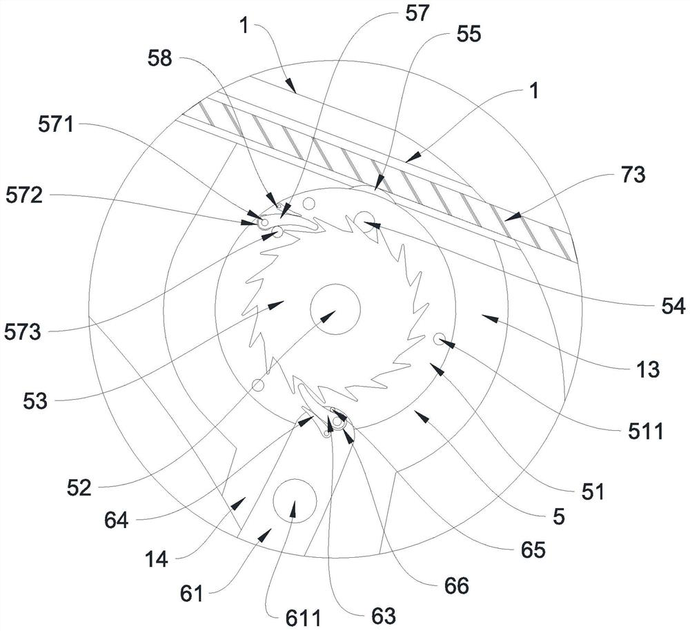
[0023] see Figure 1 to Figure 5 , a scissors instrument for use in spinal surgery incisions, including a base body 1, a push mechanism 2, a fixed forceps knife 3, a moving forceps knife 4, a linkage mechanism 5 and a driving mechanism 6.

[0024] Wherein, the above-mentioned seat body 1 is in the curved shape of "7" to avoid disturbing the field of vision during the cutting process. One end of the seat body 1 is provided with a handle 12, which is convenient for personnel to grasp, and the other end of the seat body 1 is provided with a pliers arm 11. Arm 11 connects pincer head and stretches into the body, and fixed pincer knife 3 is provided with connecting portion 31, and connecting portion 31 is fixedly connected with pincer arm 11 ends, and movable pincer knife 4 is prov...


PUM

PropertyMeasurementUnit
Diameteraaaaaaaaaa

Abstract

The invention relates to the technical field of medical instruments, and discloses a rod cutting instrument used in a spinal surgical incision, the rod cutting instrument comprises a seat body, a pushing mechanism, a fixed forceps knife, a movable forceps knife, a linkage mechanism and a driving mechanism, the seat body is in a 7-shaped bent shape, one end of the seat body is provided with a handle, the other end of the seat body is provided with a forceps arm, the fixed forceps knife and the movable forceps knife are arranged at the end of the forceps arm, and the linkage mechanism is connected with the linkage mechanism. A sliding groove is formed in the clamp arm, the pushing mechanism is located in the sliding groove, and the pushing mechanism is connected with the movable clamp knife; a linkage cavity is formed in the seat body, a driving groove is formed in the lower side of the driving cavity in a communicating mode, a guide sliding hole is formed in the upper side of the linkage cavity in a communicating mode, the linkage mechanism is located in the linkage cavity, the driving mechanism is located in the driving groove, and the linkage mechanism is connected between the driving mechanism and the pushing mechanism; the problems that in the scoliosis deformity correction operation process, due to limitation of a cutting tool, a fixing rod needs to be taken down for cutting, time and labor are wasted in the cutting process, and operation risks exist are solved.

Description

technical field [0001] The invention relates to the technical field of medical appliances, in particular to a scissors instrument used in spinal surgery incisions. Background technique [0002] Nowadays, scoliosis correction surgery mainly uses screw-rod system for fixation. In the correction of scoliosis, it is necessary to fix the fixed rod on the spine, and then gradually reset the scoliotic spine through the fixed rod. After the spine is reset, the fixed rod will grow a part, which needs to be cut off, but at this time The fixation rod has been fixed to the spine, and the strength and hardness of the fixation rod are relatively high. Today’s cutting tools are too large to directly cut off the fixation rod fixed on the spine. Currently, cutting the fixation rod can only maintain the spine in other ways. Then remove the fixing rod and cut it to a suitable length, then fix the fixing rod to the spine again, take off the fixing rod and fix it again, and generally use large ...

Claims


Application Information

Patent Timeline
IPC IPC(8): A61B17/92A61B17/88A61B17/70
CPCA61B17/92A61B17/8863A61B17/7002A61B17/7074
Inventor 祝春阳
Owner 杭州知橙生物科技有限公司
Learn More