Distributed Generation Power System

a power system and distribution technology, applied in the direction of electric devices, process and machine control, instruments, etc., can solve the problems of higher system wiring loss, increased maintenance problems, and additional drawbacks of micro-inverters b>11/b>

Inactive Publication Date: 2010-07-29
UNIQUE MOBILITY
View PDF24 Cites 38 Cited by
  • Summary
  • Abstract
  • Description
  • Claims
  • Application Information

AI Technical Summary

Problems solved by technology

However, the micro-inverters 11 have additional drawbacks.
First, the AC wiring lengths are longer, which can create higher system wiring losses, due to lower voltage transmission (120 VAC (AC volts) or 240 VAC) through such longer lengths of wire.
Second, the micro-inverters 11, which are mounted underneath each PV module 8, can create or exacerbate maintenance problems because of their distributed, inaccessible locations, should their be any damage, failures, recalls or other maintenance requirements at the micro-inverter level.
Interactions with utility providers has been limited to two different approaches.

Method used


Image

  • Distributed Generation Power System
  • Distributed Generation Power System
  • Distributed Generation Power System

Examples


Embodiment Construction

[0032]Exemplary embodiments of the present disclosure as described herein have been developed to make emission-free energy production a more viable, sustainable and economically competitive alternative to conventional electricity production and distribution systems and to provide dynamic interaction with utility providers.

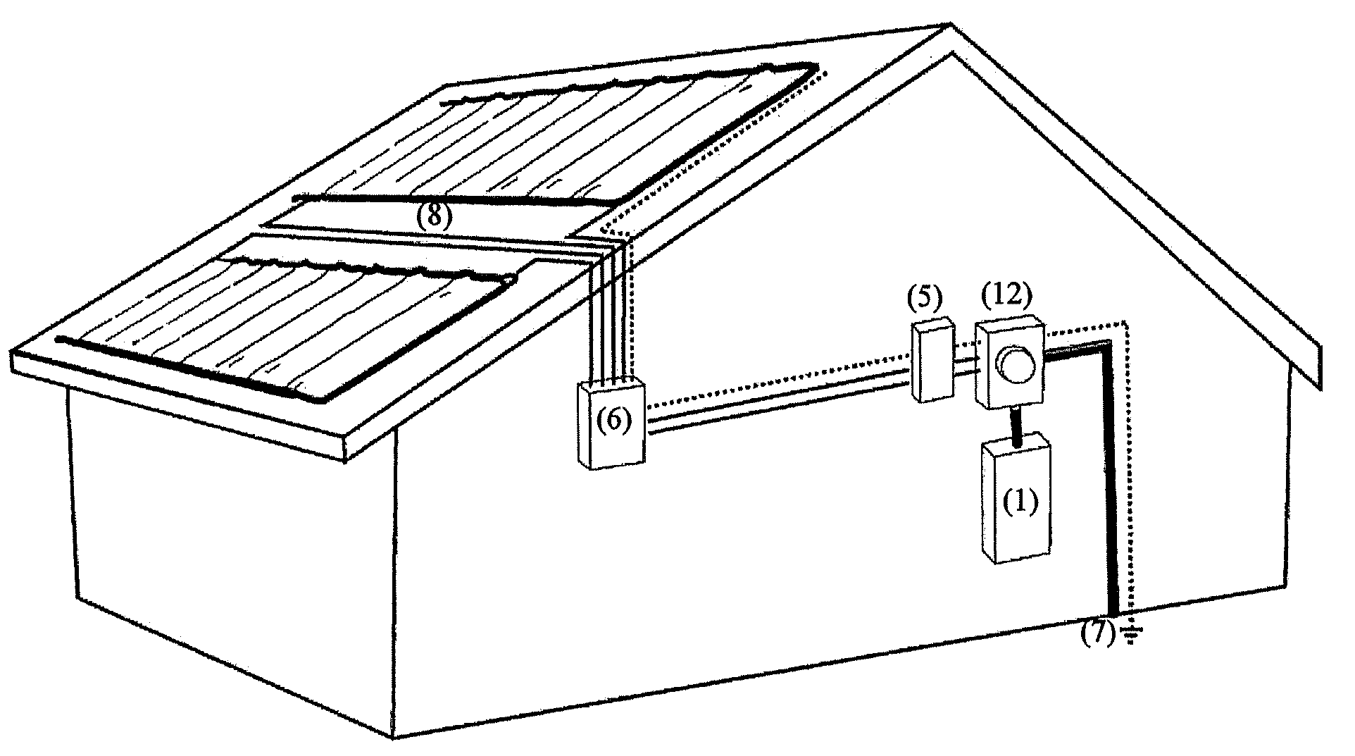
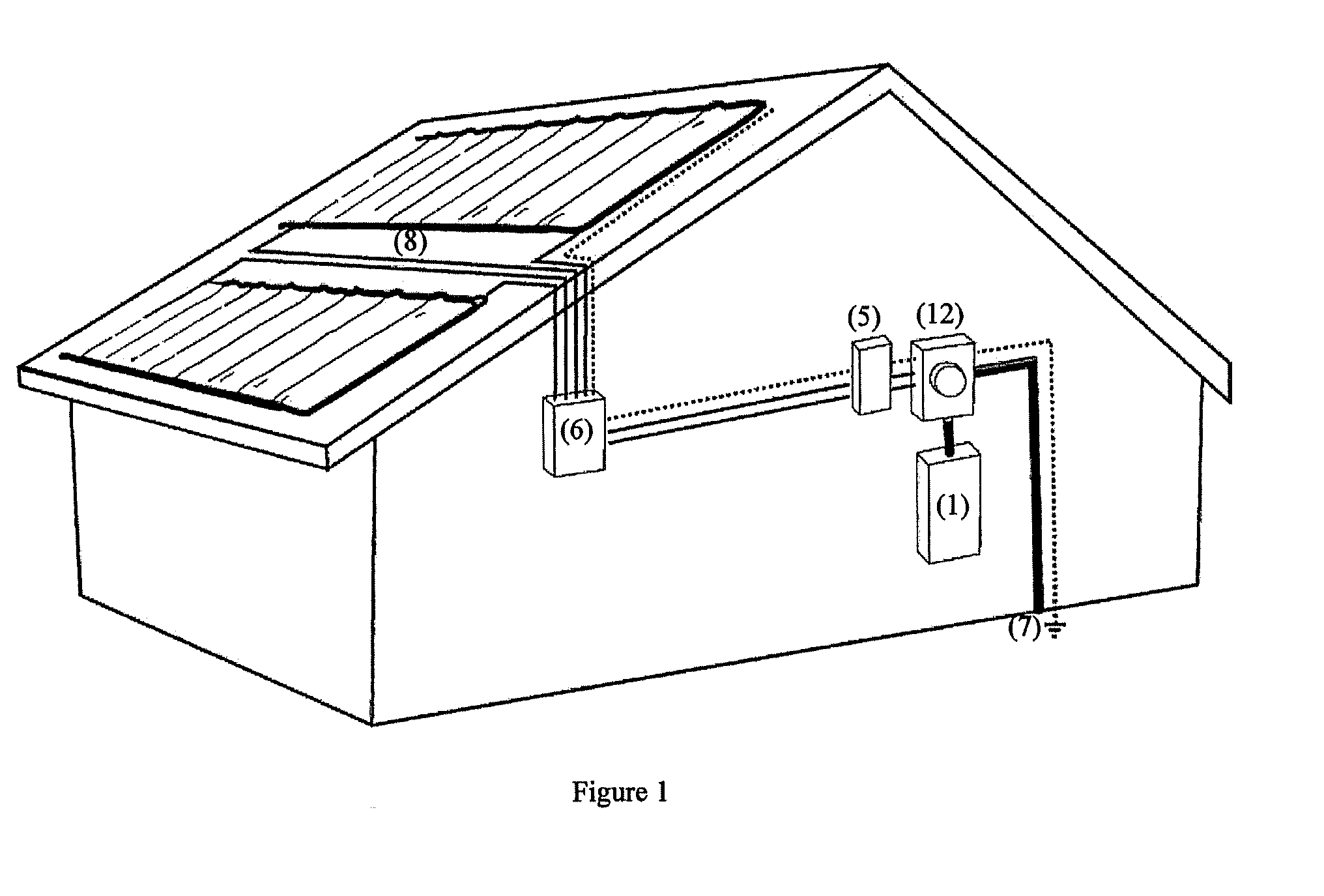
[0033]FIG. 1 is a diagram illustrating an exemplary integrated electric utility meter and inverter system according to at least one embodiment. Elements of the exemplary system illustrated in FIG. 1 that have the same reference numeral as the elements illustrated in FIGS. 10-12 have functions similar to the elements illustrated in FIGS. 10-12 and will not be described further, unless otherwise noted.

[0034]Reference numeral 12 denotes a smart, highly integrated electric utility meter and inverter. The term “integrated electric utility meter and inverter” will hereinafter be abbreviated as “integrated inverter-meter,” unless otherwise noted. A DC disconnect 5 is comm...


PUM


Abstract

A distributed generation power system includes a utility meter connectable to an electric utility provider and configured to communicate with a communication device of the utility provider, an inverter configured to convert distributed generation (DG) power generated by a DG power source into AC power, and an intermediate connector configured to connect the meter and inverter to constitute an integrated inverter-meter. The integrated inverter-meter is configured to communicate a measured aggregate amount of the DG power and a measured amount of power consumed on site to the communication device of the utility provider. The inverter is configured to receive at least one operating command from the meter and / or the communication device of the utility provider. The integrated inverter-meter is configured to alter a control parameter of the operating state of the inverter in accordance with the operating command, and to alter an operating state of the DG power source and / or at least one load connectable to the site.

Description

FIELD OF THE DISCLOSURE[0001]The present disclosure relates to a distributed generation power system having an integrated electric utility meter and inverter system, including the physical design, placement and interconnection of the integrated electric utility and inverter system.BACKGROUND[0002]Recent scientific and political efforts have endeavored to reduce emissions of greenhouse gases into the earth's atmosphere. Proposals to limit carbon emission, impose caps on a country's carbon emissions, and tax entities based on their carbon emissions are gaining in popularity. In recent years, many renewable energy incentives and mandates have been introduced at local, state, federal and international levels.[0003]One mainstream application of clean, renewable energy is through solar power, i.e., photovoltaic (PV) systems. Increasingly, PV installations are connected directly to conventional electrical utility grids for distributed residential and commercial applications, rather than of...

Claims


Application Information

Patent Timeline
Patent Type & Authority Applications(United States)
IPC IPC(8): G01R21/00G06F1/26
CPCH02J3/38
Inventor ZOLOT, MATTHEW D.
Owner UNIQUE MOBILITY
Why Eureka
Try Eureka