Channel joining system with a mounting channel and a joining part for joining the mounting channel to a support

a channel joining system and mounting channel technology, which is applied in the direction of machine supports, threaded fasteners, rod connections, etc., can solve the problems of not always being guaranteed, the mounting channel cannot be arranged, and the logistics work is too high for the user and the manufacturer, etc., to achieve the effect of convenient handling

Inactive Publication Date: 2010-08-05
HILTI AG
View PDF15 Cites 24 Cited by
  • Summary
  • Abstract
  • Description
  • Claims
  • Application Information

AI Technical Summary

Benefits of technology

[0011]It is an object of the present invention to provide a channel joining system that is easy to ...

Problems solved by technology

A drawback of this prior-art approach is that, in order to be installed, the channel joining system first has to be dismantled and secured on each side of the support with two nuts on each side, which is very laborious.
A drawback of this prior-art approach is that differently configured parts are needed for different mounting channel heights and support dimensions, which calls for excessively high logist...

Method used


Image

  • Channel joining system with a mounting channel and a joining part for joining the mounting channel to a support
  • Channel joining system with a mounting channel and a joining part for joining the mounting channel to a support
  • Channel joining system with a mounting channel and a joining part for joining the mounting channel to a support

Examples


Embodiment Construction

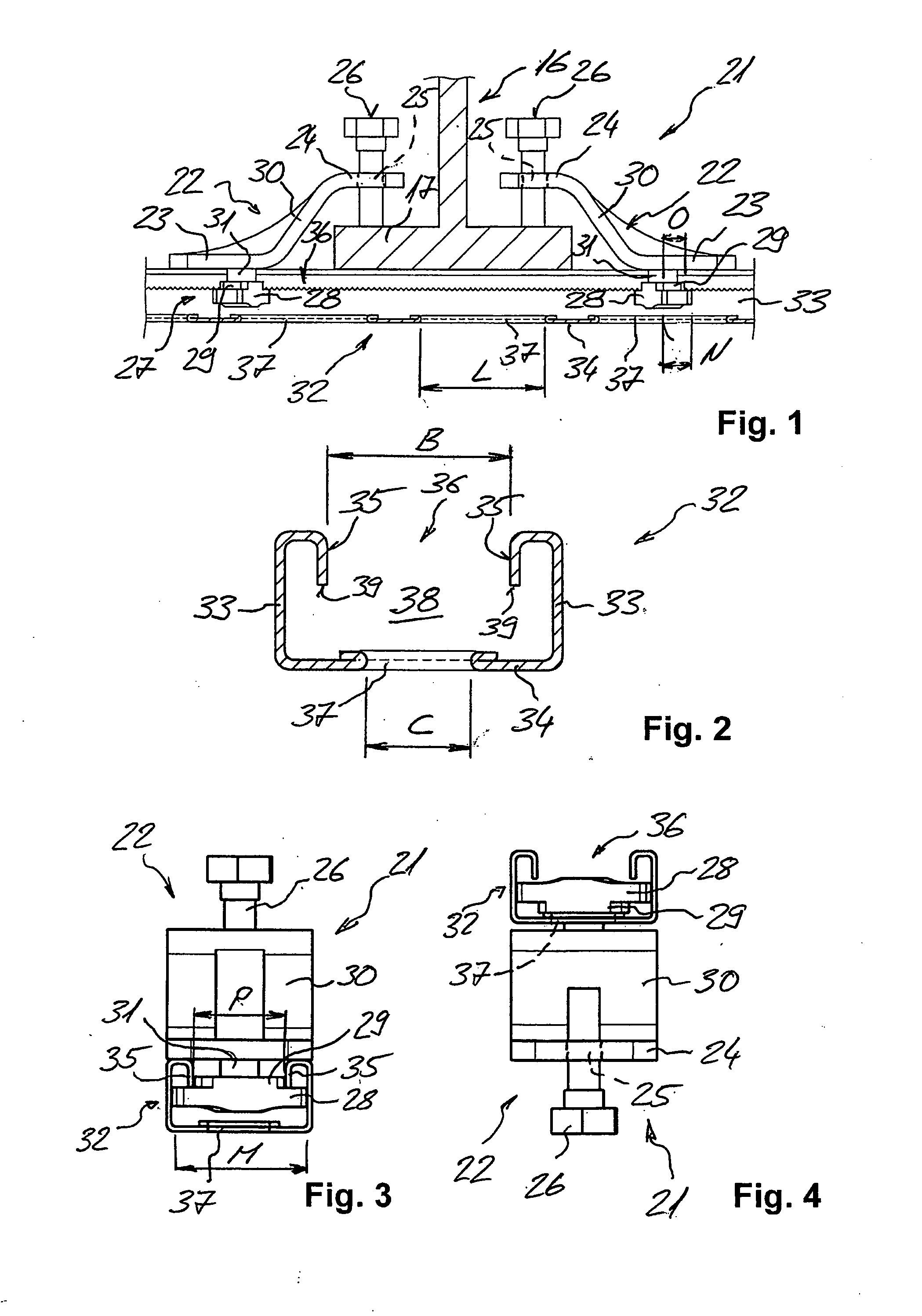
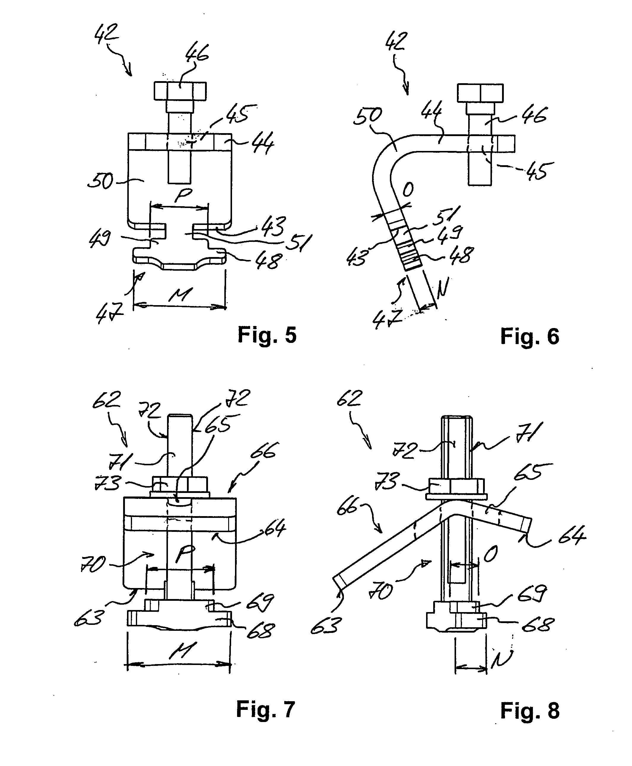
[0033]The channel joining system 21 shown in FIGS. 1 to 4 for joining a mounting channel 32 to a support has two joining parts 22 and a mounting channel 32.

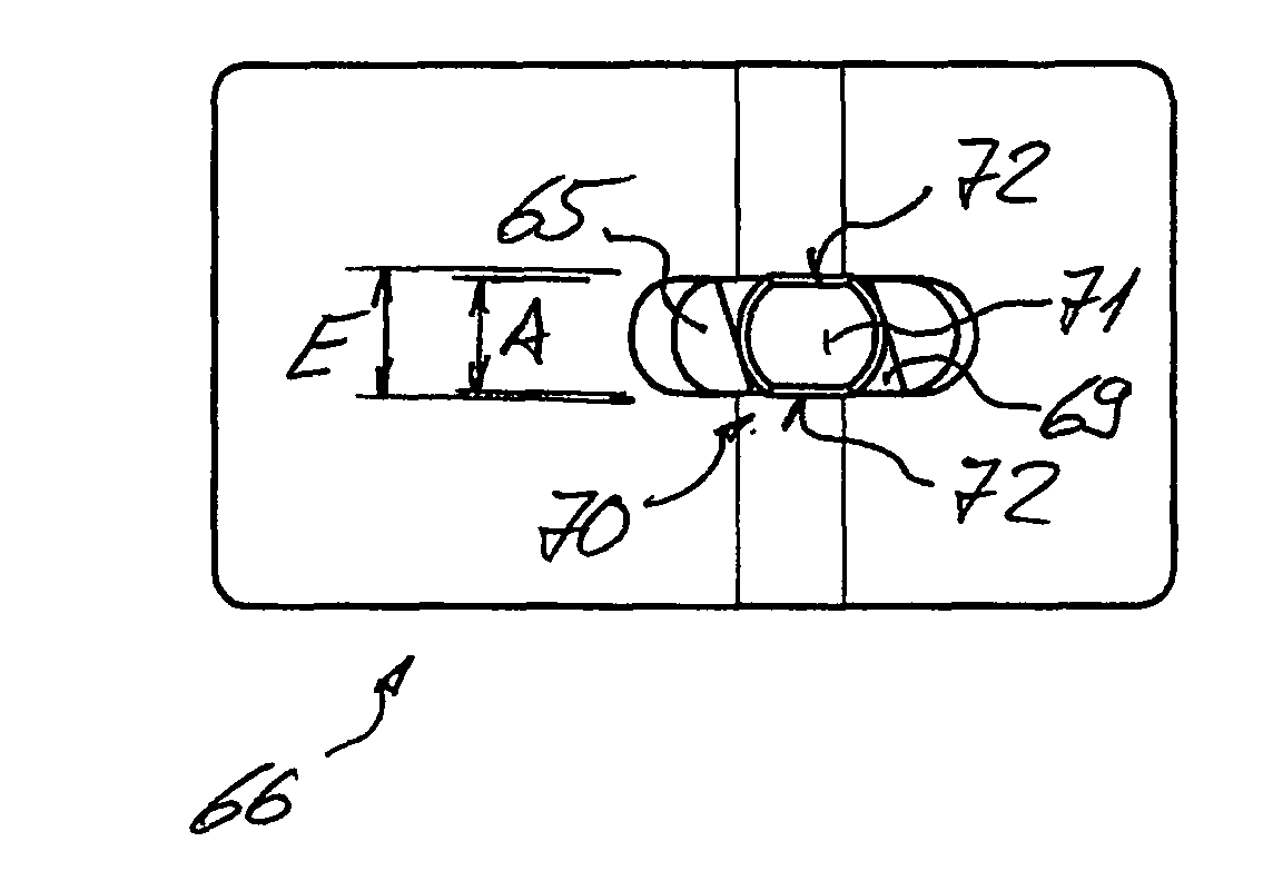
[0034]As the profile walls, the mounting channel 32 has two opposite side walls 33, a rear wall 34 that connects these side walls 33 and, opposite from this rear wall 34, an installation opening 36 that is delimited by edges 35 and that runs in the longitudinal extension of the mounting channel 32. The installation opening 36 has a clear width B that runs perpendicular to the longitudinal extension of the mounting channel 32, and this clear width B is defined by the free ends 39 of the edges 35 that are bent towards the inside. The free ends 39 of the edges 35 are provided with teeth. In the rear wall 34, several fastening openings 37 are provided that are at a distance from each other in the longitudinal extension of the mounting channel 32 and that each have a clear length L running in the direction of the longitudinal extensio...


PUM


Abstract

The invention relates to a channel joining system (21) with a mounting channel (32) and two joining parts (22) for joining the mounting channel (32) to a support (16). The mounting channel (32) has an installation opening (36) that runs along the longitudinal extension of the mounting channel (32), that has a clear width (B) running perpendicular to the longitudinal extension and that, in one of the profile walls (34), has several fastening openings (37) that are at a distance from each other in the longitudinal extension of the mounting channel (32). The fastening openings (37) each have a clear length (L) running in the direction of the longitudinal extension of the mounting channel (32) and a clear width running perpendicular thereto. Each joining part (22) has a contact section (23), a holding section (24) and a fastening section (27). The fastening section (27; 47; 107) has an engaging section (28) that can be inserted into the mounting channel (32) and that can be rotated so as to engage behind the edges of the installation opening (36), the length of the engaging section (28) is greater than the clear width of the installation opening (36) but smaller than the clear length (L) of one of the installation openings (37), and the width (N) of the engaging section (28) is smaller than the clear width of the installation opening (36) and smaller than the clear width of a fastening opening (37).

Description

[0001]This claims the benefit of German Patent Application DE 10 2009 000 608.7-24, filed Feb. 4, 2009 and hereby incorporated by reference herein.[0002]The present invention relates to a channel joining system with a mounting channel and a joining part for joining the mounting channel to a support.BACKGROUND[0003]In the realm of utilities in buildings, channel systems are used to which lines, for example, for water, heating, ventilation, air-conditioning and / or electric installations can easily be attached by means of suitable joining devices such as, for example, channel nuts.[0004]For this purpose, preference is given to a so-called C-shaped mounting channel of the type known, for example, from German utility model DE 87 15 256 U1. As the profile walls, this mounting channel has two side walls arranged in parallel to each other and a rear wall that connects these side walls. The interior space enclosed by the mounting channel is accessible from the outside through an installation...

Claims


Application Information

Patent Timeline
IPC IPC(8): F16B7/04
CPCE04B1/4107H02G3/263F16B37/045
Inventor MERHAR, THOMASLIPPUNER, RALPH
Owner HILTI AG
Why Eureka
Try Eureka