Ink jet recording apparatus

Active Publication Date: 2010-08-05
MIYAKOSHI PRINTING MACHINERY
View PDF34 Cites 16 Cited by
  • Summary
  • Abstract
  • Description
  • Claims
  • Application Information

AI Technical Summary

Benefits of technology

[0019]a controller in response to the detection signal from the said fabric sensor for increasing and decreasing the rate of traction by the said traction roll.
[0028]Also, by making each of the driers movable towards and away from surfaces of the fabric, each dryer can be moved towards and away from printed surfaces of the fabric in synchronism with their passing as the unit starts and ceases driving. Possible damage of the fabric by hot air is thus effectively prevented.

Problems solved by technology

In the conventional apparatus mentioned above, with such a looped portion of fabric made free, increasing demands to rise its printing speed in recent years have tended to make its printing quality liable to influences from feeding the fabric intermittently in its ink jet recording section.
This has, however, led to the problem that a temporary load produced in the fabric supply section makes it unstable to convey the fabric and also the problem that the need to repeatedly start and cease conveying the fabric in the drying section easily causes a drying spot and makes it difficult to stably achieve uniformity in printing density and coloring.
While such a dust remover and a cloth guide are allowed to effectively function with stability in the continuous traveling state of the fabric, in the operating state needed to repeatedly start and cease conveying the fabric they cause the problem that suction to remove dust while the fabric is at a halt may cause the fabric fibers to partially distort and may make the fibers uneven in property and the problem that in the cross guide section, unevenness in mechanical load is liable to occur and longitudinal veining cannot be removed stably.

Method used


Image

  • Ink jet recording apparatus
  • Ink jet recording apparatus
  • Ink jet recording apparatus

Examples


Embodiment Construction

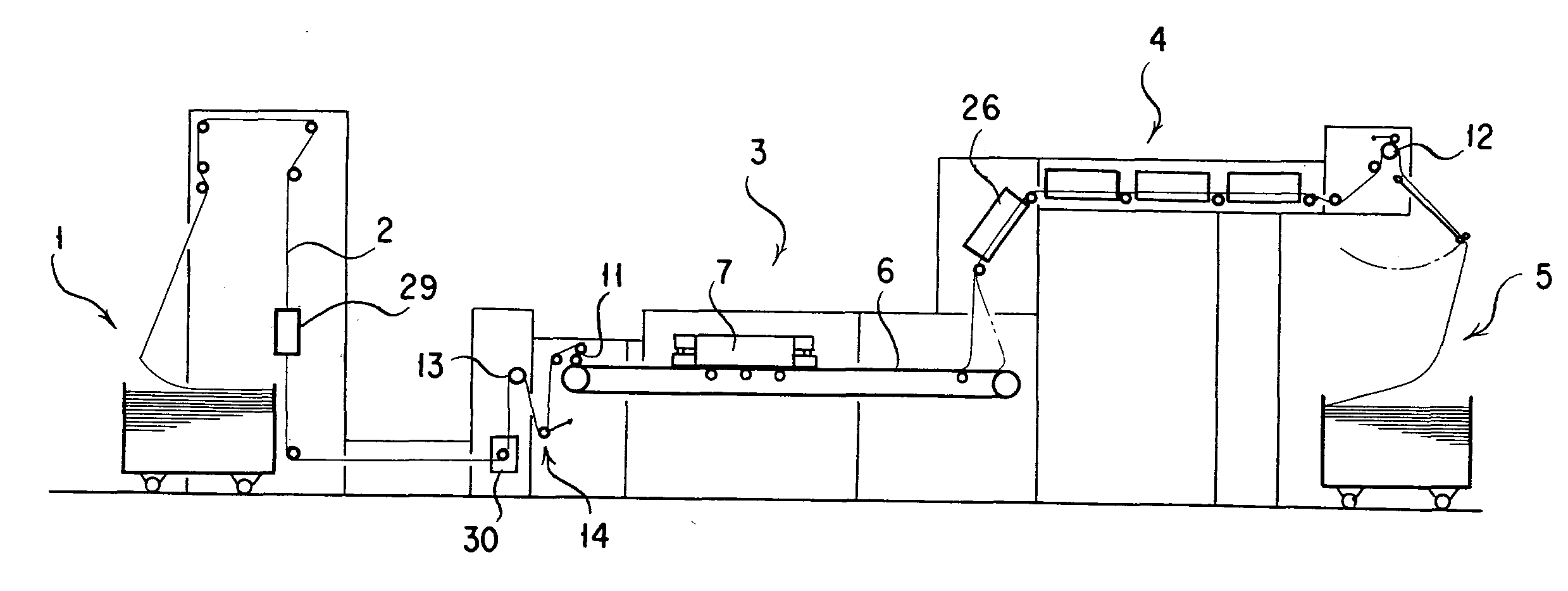
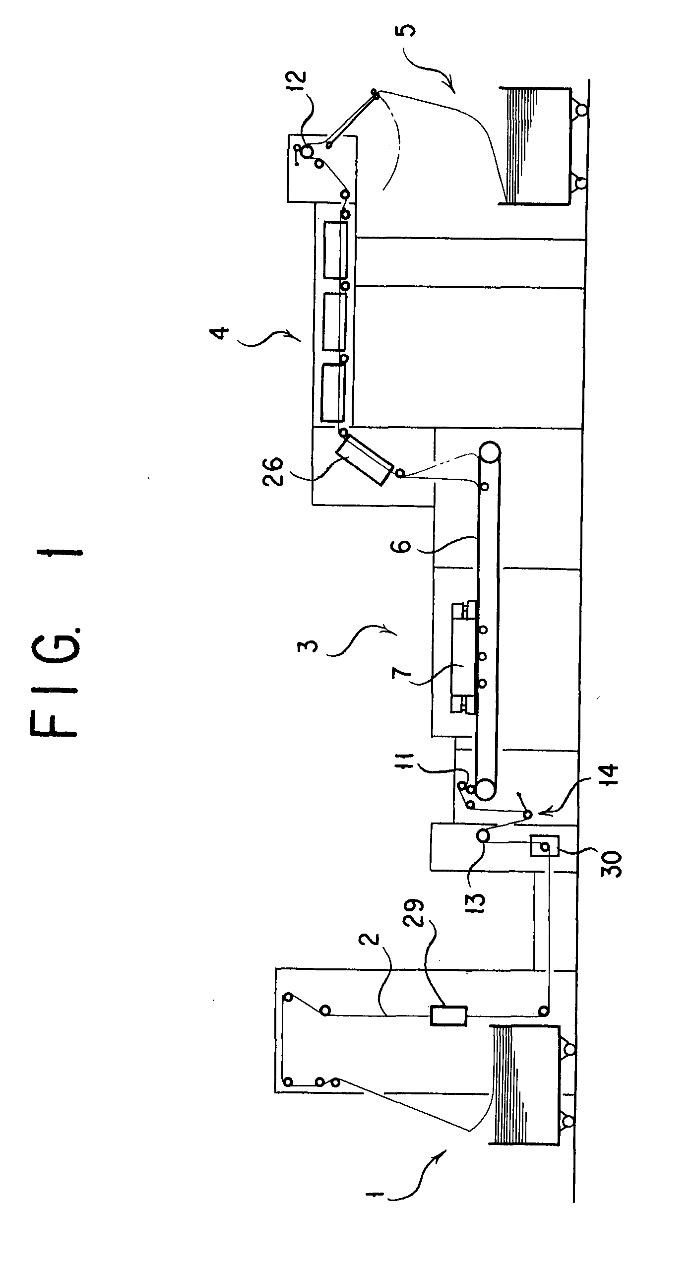
[0035]FIG. 1 is a front view that diagrammatically illustrates the makeup of an ink jet recording apparatus implemented in accordance with the present invention. The apparatus is shown to include a fabric supply section 1 that supplies a fabric 2 as a recording medium, an ink jet recording section 3 for printing on a surface of the fabric 2 with ink jet as the fabric 2 is driven to travel, a drying section 4 and a folder section 5. And, the ink jet recording section 3 comprises a conveyer 6 for conveying the fabric 2 and a recording head unit 7 of serial printing type disposed as opposed to the conveyer 6 from its upstream side.

[0036]The conveyer 6 is designed to intermittently operate, interlocked with an operation of the recording head unit 7.

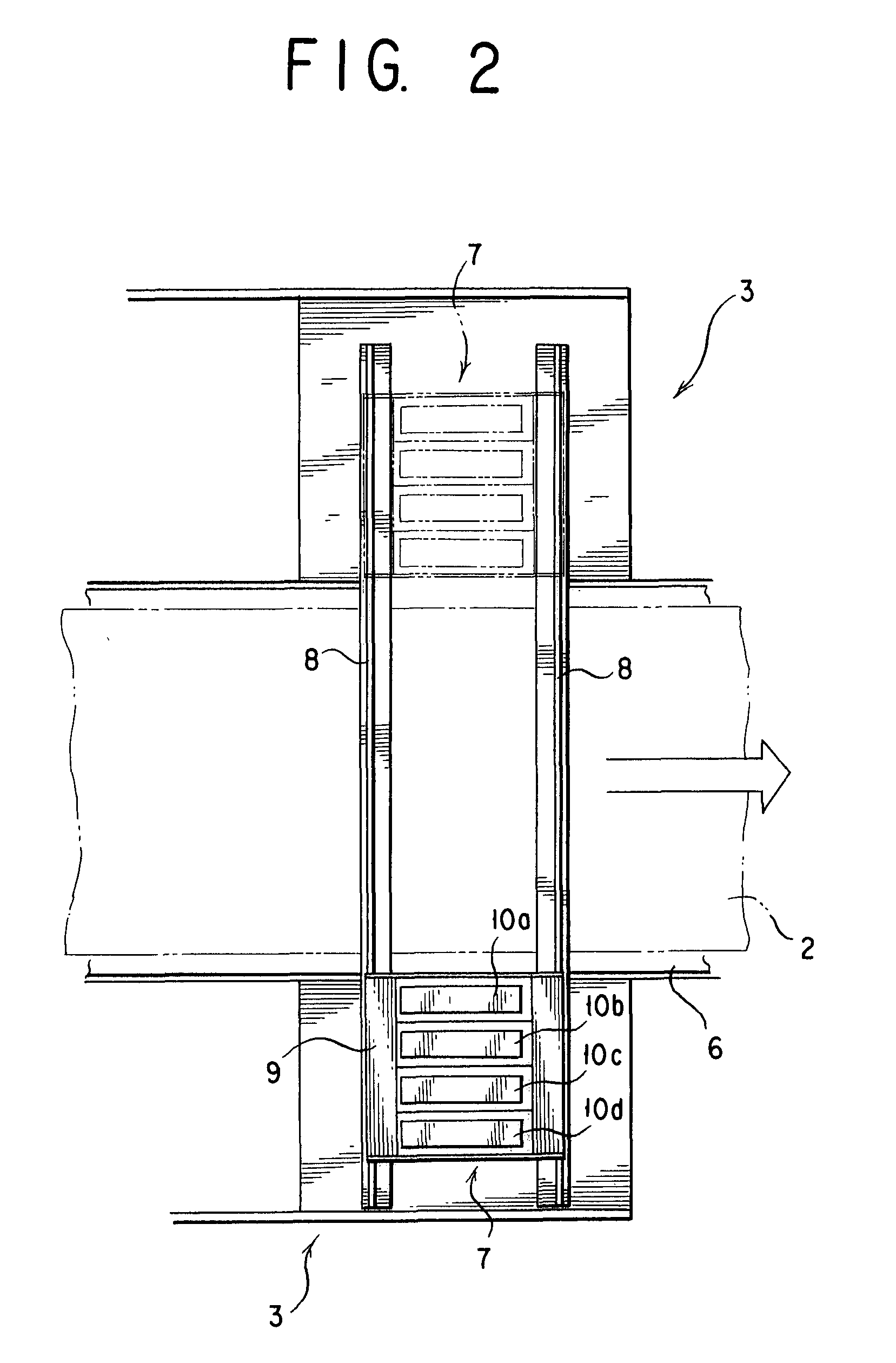
[0037]The recording head unit 7 as shown in FIG. 2 comprises a plurality of, say four (Y, M, C and K) rows of line heads 10a, 10b, 10c and 10d which are disposed on a carriage 9 movable on rails 8 and 8 in a direction orthogonal to the travel...


PUM


Abstract

An ink jet recording apparatus in which a fabric as a recording medium is intermittently conveyed in an ink jet recording section is capable of printing an image on the fabric with precision and at high quality. The ink jet recording section of serial printing type includes a conveyer for intermittently conveying the fabric. Printing on the fabric intermittently conveyed in the ink jet recording section, the fabric printing ink jet recording apparatus with the conveyer intermittently conveying the fabric while it is temporarily stuck on the conveyer, includes: a feed roll for continuously feeding the fabric onto an upstream end of the conveyer, and a dancer roll unit, the feed roll and dancer roll unit being disposed upstream of the ink jet recording section in order from upstream in the traveling direction of the fabric; and a drying section, and a traction roll for continuously pulling the fabric from a downstream end of the conveyer for unsticking the fabric from the latter, the drying section and traction roll unit being disposed downstream of the ink jet recording section in order from upstream in the traveling direction of the fabric.

Description

TECHNICAL FIELD[0001]The present invention relates to a textile printing ink jet recording apparatus designed to print on a fabric in a serial printing ink jet recording section.BACKGROUND ART[0002]In a conventional textile printing ink jet recording apparatus of serial printing in the prior art, a loop making section is provided at each of the upstream and downstream sides in the traveling direction of a fabric fed intermittently in an ink jet recording section, whereby the amount of a loop made in the loop making section is detected to control fabric conveying units on a fabric supply section at the upstream side and a drying section at the downstream side (see JP 2005-186419 A).[0003]In the conventional apparatus mentioned above, with such a looped portion of fabric made free, increasing demands to rise its printing speed in recent years have tended to make its printing quality liable to influences from feeding the fabric intermittently in its ink jet recording section. As a resu...

Claims


Application Information

Patent Timeline
IPC IPC(8): B41J2/01B41J29/38
CPCB41J3/4078B41J15/005B41J11/425
Inventor IZAWA, HIDEONAMIKI, TAKAOKATAGIRI, YASUSHIISHIKAWA, AKIRA
Owner MIYAKOSHI PRINTING MACHINERY
Why Eureka
Try Eureka