
Printing method and printing apparatus

Active Publication Date: 2010-08-05
SEIKO EPSON CORP
View PDF7 Cites 70 Cited by
  • Summary
  • Abstract
  • Description
  • Claims
  • Application Information

AI Technical Summary

Benefits of technology

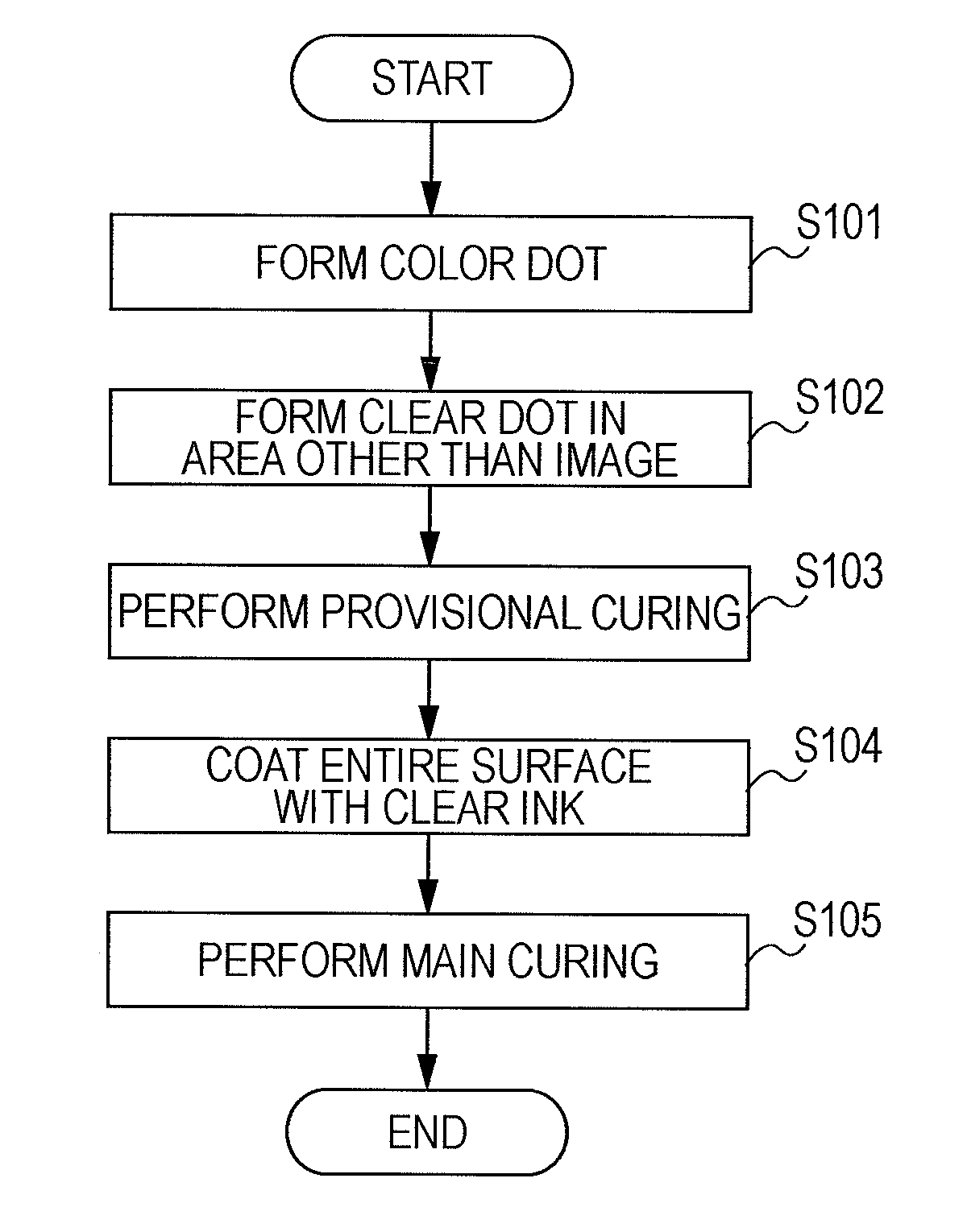
[0007]An advantage of some aspects of the invention is that it provides a printing method and a printing apparatus capable of suppressing degradation of the image quality due to aggregation of ink.
[0009]According to the above-described printing method, the process dots are formed in areas other than an image area. Accordingly, degradation of the image quality due to aggregation of the process solution can be suppressed.
[0022]According to the above-described printing method, background dots are formed in areas other than the image area. Accordingly, degradation of the image quality due to aggregation of the process solution can be suppressed.

Problems solved by technology

However, only by coating the entire surface with a process solution such as clear ink after an image is formed by using color ink, the clear ink is aggregated in the areas in which the image is not printed, whereby the gloss may be not uniform.

Method used


Image

  • Printing method and printing apparatus
  • Printing method and printing apparatus
  • Printing method and printing apparatus

Examples


first embodiment

Summary of First Embodiment

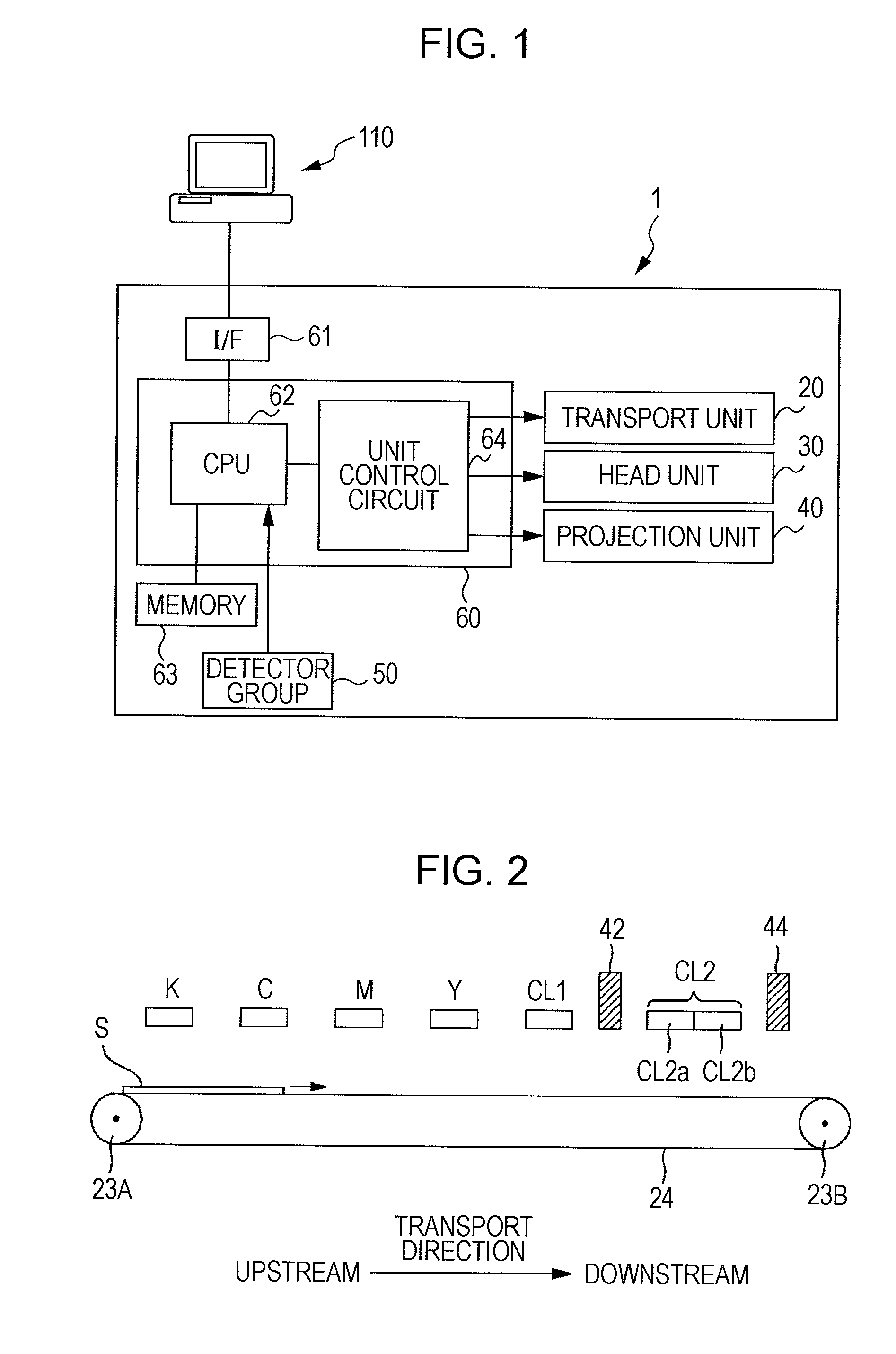
[0125]In the first embodiment, an image constituted by color dots is printed by ejecting color ink from heads for color ink, and clear dots are formed in areas other than an image area by ejecting clear ink from the first head CL1 for clear ink. Then, after UV for provisional curing is emitted onto the color dots and the clear dots from the provisional-curing irradiation section 42, the entire surface is coated with clear ink by the second clear head CL2, and UV for main curing is emitted onto the clear ink, with which the entire surface is coated, from the main-curing irradiation section 44. Accordingly, differences in heights (unevenness) can be decreased, and aggregation of the clear ink cannot easily occur. As a result, uniform gloss can be acquired.

[0126]In addition, when the clear dots are formed in areas other than the image area, the clear dots are formed so as not to be in contact with the color dots. Then, before the color dots and the clear dots...

second embodiment

Summary of Second Embodiment

[0144]In the second embodiment, the provisional-curing irradiation sections 42a to 42e are disposed on the downstream sides of each corresponding head of the heads for color ink and heads for clear ink in the transport direction, and UV irradiation for provisional curing is performed right after formation of color dots of each color and clear dots by the corresponding provisional-curing irradiation sections. Accordingly, the formation of color dots in an image area, UV irradiation for provisional curing, formation of clear dots in areas other than the image area, and UV irradiation for provisional curing are performed. Then, the entire surface is coated with clear ink by the second clear head CL2, and UV irradiation for main curing is performed for the clear ink, with which the entire surface is coated, by the main-curing irradiation section 44. Accordingly, also in the second embodiment, differences in heights (unevenness) can be decreased, and aggregati...

third embodiment and first embodiment

Difference Between Third Embodiment and First Embodiment

[0151]In the third embodiment, a second head CL2 as shown in FIG. 2 is disposed as a head for clear ink, and an irradiation section 45 that is used for both provisional curing and main curing is disposed as an UV irradiation section.

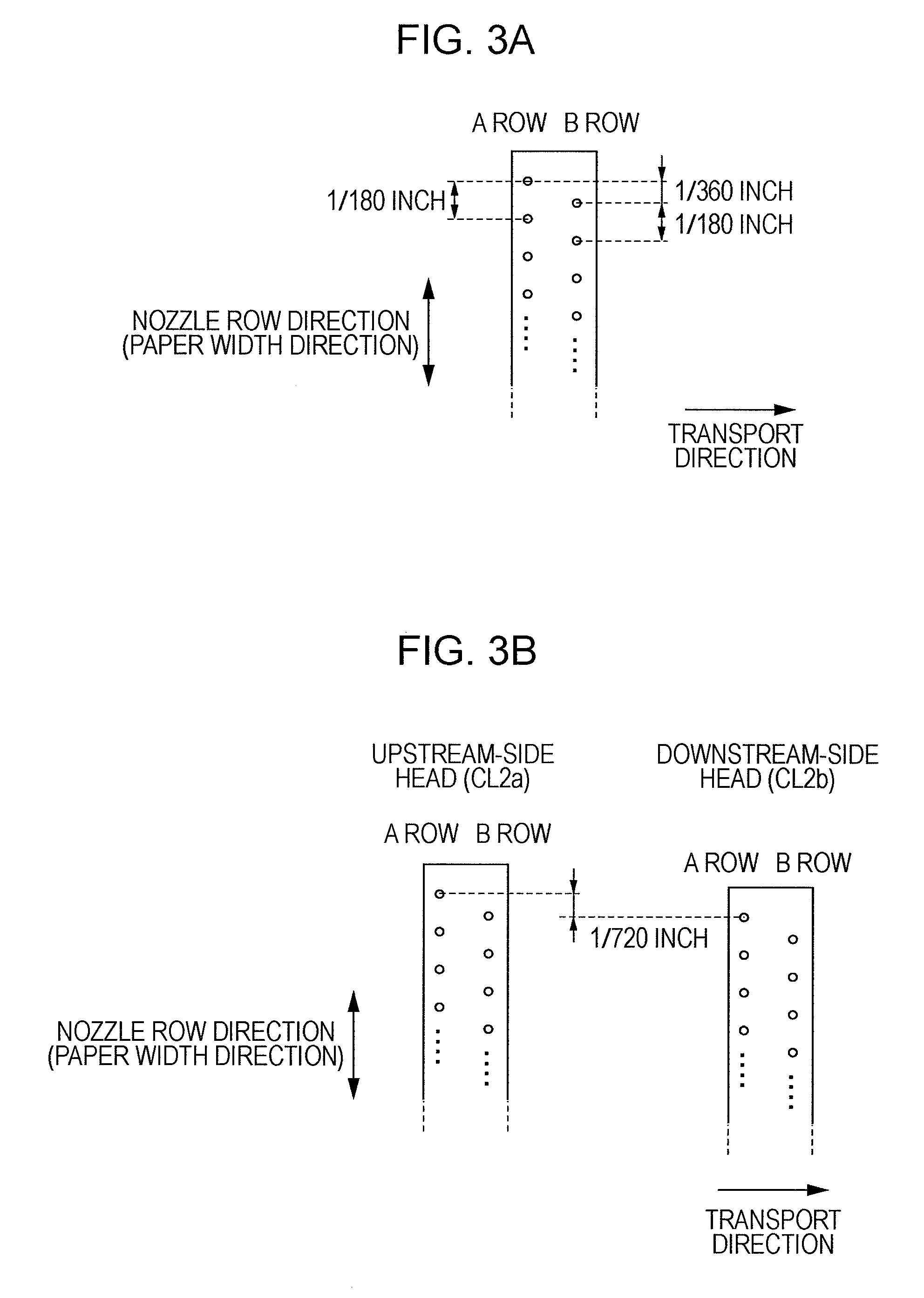
[0152]The second head CL2 is disposed on the downstream side in the transport direction relative to the heads for color ink. In addition, as described above, the second head CL2 includes an upstream head CL2a and a downstream head CL2b. The arrangement of the above-described heads is as shown in FIG. 3B. One of the upstream head CL2a and the downstream head CL2b, to be described later, is commonly used in both cases including a case where clear dots are formed in areas, in which an image is not formed, and a case where the entire surface is coated with ink.

[0153]The irradiation section 45 is disposed on the downstream side in the transport direction relative to the second head CL2. In addition, the ...


PUM


Abstract

There is provided a printing method that is performed by using a first nozzle ejecting color ink that is used for printing an image on a medium and is cured in a case where irradiation of an electromagnetic wave is received, a second nozzle ejecting a process solution that is used for processing the surface of the medium and is cured in a case where irradiation of an electromagnetic wave is received, and an irradiation unit emitting the electromagnetic wave. The printing method includes printing an image constituted by color dots on the medium by ejecting the color ink from the first nozzle so as to form the color dots on the medium and forming process dots in areas other than the image on the medium by ejecting the process solution from the second nozzle, emitting the electromagnetic wave onto the color dots and the process dots, coating the color dots and the process dots with the process solution after the electromagnetic wave is emitted onto the color dots and the process dots, and emitting the electromagnetic wave onto the process solution with which the color dots and the process dots are coated.

Description

BACKGROUND[0001]1. Technical Field[0002]The present invention relates to a printing method and a printing apparatus.[0003]2. Related Art[0004]Printing apparatuses that perform printing by using ink (for example, UV ink) that is cured by receiving irradiation of an electromagnetic wave (for example, an ultraviolet ray (UV)) are known. In such printing apparatuses, ink is ejected onto a medium (a paper sheet, a film, or the like) from a nozzle, and then an electromagnetic wave is emitted onto dots formed on the medium. Accordingly, the dots are cured so as to be fixed to the medium. Thus, excellent printing can be performed even for a medium that cannot easily absorb liquid (for example, see JP-A-2000-158793).[0005]When an image is printed by using UV ink, gloss is different between an area in which an image is printed and an area in which an image is not printed. Thus, a method in which the entire surface of the medium is coated with colorless transparent UV clear ink (one type of a ...

Claims


Application Information

Patent Timeline
IPC IPC(8): B41J2/01
CPCB41J2/2114B41J11/002B41J2/211B41M7/0081B41J2/2107B41J29/38B41J11/00214
Inventor MITSUZAWA, TOYOHIKO
Owner SEIKO EPSON CORP
Learn More