Shock absorbing cockpits

a cockpit and shock absorption technology, applied in the field of boats, can solve problems such as the prior art of inventing structures, and achieve the effect of reducing the risk of collision

Active Publication Date: 2010-08-12
WERNER TODD C
View PDF5 Cites 2 Cited by
  • Summary
  • Abstract
  • Description
  • Claims
  • Application Information

AI Technical Summary

Benefits of technology

[0020]The invention therefore allows boat buyers to avoid the purchase of expensive, bulky shock-absorbing seats that fall short of providing adequate shock protection. Ordinary, comfortable seats may be chosen instead because the shocks are handled by the cockpit cushioning means, thereby obviating the need for shock-absorbing individual seats.
[0026]The lower frame includes a leading transversely disposed cylindrical member that extends between the stringers of the upper frame in rotatably mounted relation thereto and a trailing transversely disposed cylindrical member that extends between the stringers of the upper frame in rotatably mounted relation thereto. The leading and trailing cylindrical members are interconnected by a pair of transversely spaced apart, longitudinally disposed support members that are coplanar at their respective leading ends with the stringers of the upper frame but spaced inwardly therefrom, i.e., closer to the longitudinal axis of the watercraft. The trailing end of each support member is bent away from said longitudinal axis so that the respective trailing ends of each support member is positioned directly below the respective trailing ends of the stringers of the upper frame. This enables the air bags and shock absorbers to be positioned between top brackets connected to the stern end of the stringers and bottom brackets connected to the stem end of the support members.
[0028]An important advantage of the primary embodiment of the invention is that it protects the cockpit as a whole against shocks, thereby protecting occupants as well as equipment.
[0029]A related advantage is that it obviates the need for expensive shock-absorbing seats.

Problems solved by technology

The inventive structure contravenes the prior art by not providing improvements to the structure of individual seats.

Method used


Image

  • Shock absorbing cockpits
  • Shock absorbing cockpits
  • Shock absorbing cockpits

Examples


Embodiment Construction

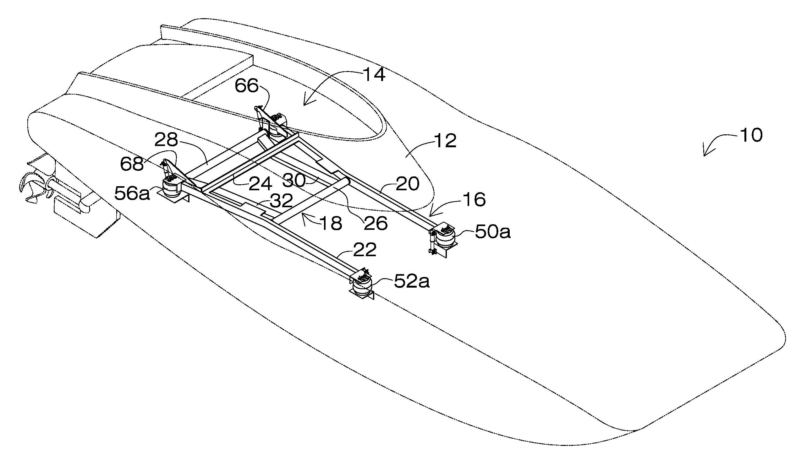
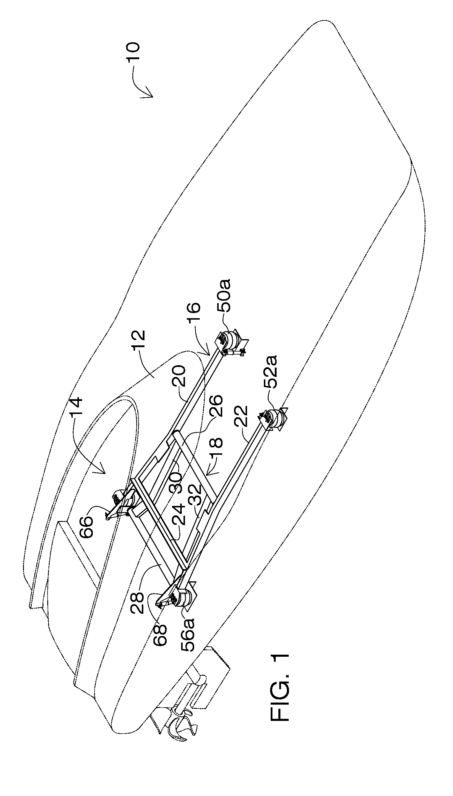
[0052]Referring now to FIG. 1, it will there be seen that a high performance watercraft equipped with the novel cockpit shock-absorbing means is denoted as a whole by the reference numeral 10.

[0053]Watercraft 10 has a windshield 12 and an open cockpit 14 but the invention has equal utility with open or closed cockpits.

[0054]The shock-absorbing support structure for the cockpit includes an upper frame denoted 16 as a whole and a lower frame denoted 18 as a whole.

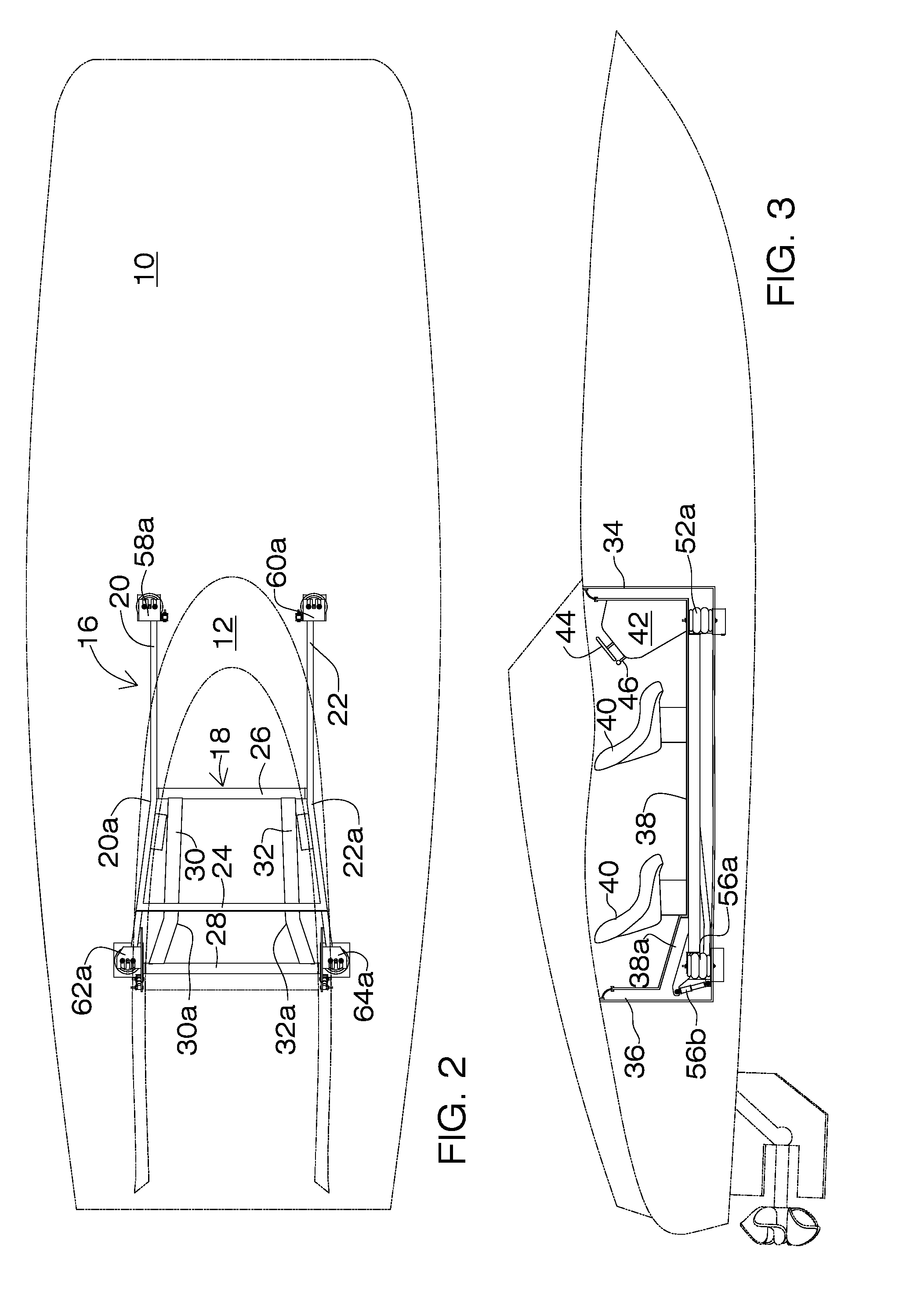
[0055]As depicted in FIGS. 1 and 2, upper frame 16 includes port stringer 20 and starboard stringer 22. The stringers are parallel to one another and transversely spaced apart from one another, interconnected by transversely disposed angle member 24. Each stringer is bent outwardly as at 20a. 22a relative to a longitudinal axis of watercraft 10 about mid-length thereof so that the respective trailing ends of the stringers are spaced further apart than the respective leading ends of the stringers.

[0056]Lower frame 18 includes ...


PUM


Abstract

A watercraft cockpit includes a floor, sidewalls and forward and rearward bulkheads. A frame assembly having four corners supports the cockpit and includes an upper frame and a lower frame that are rotatably connected to one another. A pair of shock-absorbing members is provided at each of the four corners of the frame so that the entire cockpit is isolated from shocks. By cushioning the entire cockpit as a whole, the need for individual shock-absorbing seats is obviated. The walls of the cockpit are spaced apart from the sidewalls of the watercraft and are interconnected to the sidewall of the watercraft by a flexible member so that the sidewalls of the watercraft move up and down in response to shocks independently of the walls of the cockpit. Each shock-absorbing member preferably includes an airbag and a dashpot but other shock-absorbing members are within the scope of the invention.

Description

BACKGROUND OF THE INVENTION[0001]1. Field of the Invention[0002]This invention relates, generally, to boats. More particularly, it relates to shock-absorbing means for the cockpit of a speedboat or the pilot's lounge of a pleasure craft.[0003]2. Description of the Prior Art[0004]Occupants of a speedboat, whether a driver, navigator, throttleman, or passenger, are confined for safety purposes in a cockpit which may be closed or open. A closed cockpit is a full enclosure including a floor, walls, and ceiling whereas an open cockpit may lack a ceiling or walls that extend all the way to an overhead cover.[0005]The pilot's lounge of a slower pleasure boat has much the same structure as a speedboat cockpit. The different names for essentially the same structure arise primarily because the high speeds attained by speedboats make the name cockpit more suitable instead of the more leisurely-sounding pilot's lounge.[0006]Occupants of the cockpit, whether the cockpit is open or closed, and wh...

Claims


Application Information

Patent Timeline
Patent Type & Authority Applications(United States)
IPC IPC(8): B63B29/02
CPCB63B17/0081
Inventor WERNER, TODD C.
Owner WERNER TODD C
Why Eureka
Try Eureka