Pedal Kickstand

a kickstand and pedal technology, applied in the field of bicycles, can solve the problem of increasing the weight of the whole bicycle, and achieve the effect of eliminating the potential hazard caused by the conventional kickstand being exposed

Inactive Publication Date: 2010-08-12
DONGGUAN SHUNCHUEN METAL PROD
View PDF10 Cites 8 Cited by
  • Summary
  • Abstract
  • Description
  • Claims
  • Application Information

AI Technical Summary

Benefits of technology

[0010]The present invention is mounted to a bicycle, and the pedal kickstand is connected to the crank of the bicycle; when the earth stand is unfolded outward for a specific angle, the bicycle can be held upright; for the pedal kickstand provided by the present inv...

Problems solved by technology

Both a single-pillar type kickstand and a double-pillar type kickstand all have certain disadvantages: for a single-pillar type kickstand, the bicycle is stood by forming a supporting surface via the touchdown points of the front wheel, the rear wheel, and the single-pillar kickstand, so, the single-pi...

Method used


Image

  • Pedal Kickstand
  • Pedal Kickstand
  • Pedal Kickstand

Examples


embodiment 1

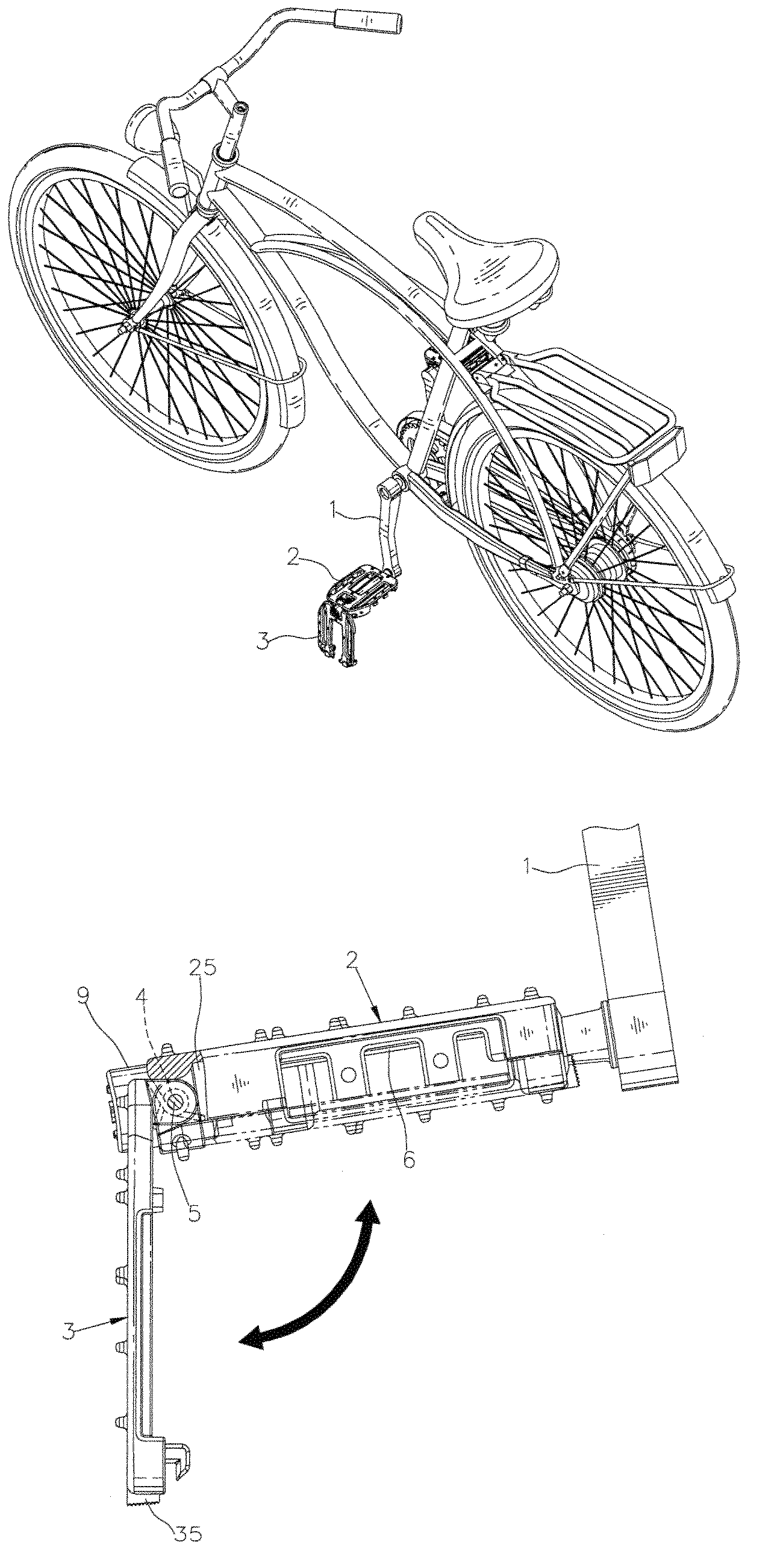
[0028]Referring to FIGS. 3-6, mainly an earth stand 3 is mounted to the outer side of the pedal 2 by pin joint; the lower end of the pedal 2 is provided with an axis seat 23, and the axis seat 23 can be connected to the crank 1 by pin joint; an outer pivot terminal edge 24 that is connected to the earth stand 3 by pin joint is at the outside of the pedal 2, and the outer pivot terminal edge 24 is provided with a socket joint hole 26 opposite to the axis seat 23; an interval gap 25 is preliminarily provided between the socket joint hole 26 and the axis seat 23, and the socket joint hole 26 and the axis seat 23 are coaxial.

[0029]At least one torsion spring 4 is mounted between the pin joint end of the pedal 2 and the earth stand 3, so as to make the earth stand 3 capable of being unfolded by being twisted elastically, and the earth stand 3 can be folded corresponding to the pedal 2 to be fixed as the form of a pedal with its two surfaces capable of being pedaled. In the present embodi...

embodiment 2

[0037]Referring to FIGS. 10-13, mainly an earth stand 3 is mounted to the outer side of the pedal 2 by pin joint; the pedal 2 is provided with an axis seat 23, and the axis seat 23 is provided with a through hole 23a; a slide bar 10 is inserted from one side of the through hole 23a, and the slide bar 10 is connected to two bearings 11 by socket joint; the end of the slide bar 10 that is inserted into the through hole 23a is provided with a locking bolt 12, and the locking bolt 12 limits the bearing 11 to slide off from one side of the slide bar 10; the outer extension end of the slide bar 10 is connected to the bicycle crank 1, and the pedal 2 is capable of rotating around the slide bar 10.

[0038]The pin joint end of the pedal 2 is provided with pivot ears 2a, and the pivot ear 2a is provided with a perforation 2a1; the pivot ear 2a is provided with a ring groove 2a2 for containing a torsion spring 4; the pin joint end of the earth stand 3 is provided with pivot holes 3a, and the two...


PUM


Abstract

The present invention relates to the technical field of bicycles, particularly relates to a pedal kickstand. The pedal kickstand of the present invention comprises a pedal, and an earth stand capable of being folded mounted to the outer side of the pedal by pin joint; when the earth stand is unfolded outward to stand on the ground, the bicycle can be held upright steadily. The present invention is mounted to a bicycle and the pedal kickstand is connected to the crank of the bicycle; when the earth stand is unfolded outward for a specific angle, the bicycle can be held upright; for the pedal kickstand provided by the present invention directly utilizes the pedal as the kickstand, the potential hazard caused by the conventional kickstand being exposed can be eliminated, and at the same time, it will not cause the weight problem of additionally mounting a kickstand; it is more beautiful as a whole.

Description

BACKGROUND OF THE INVENTION[0001]1. Field of the Invention[0002]The present invention relates to the technical field of bicycles, particularly relates to a pedal kickstand that has the effect of supporting a bicycle.[0003]2. Description of the Related Art[0004]Bicycles will all be provided with a kickstand for holding the bicycles upright when not being ridden. Conventional bicycle kickstands are all additionally fixed to the bicycles as an individual component. Conventional bicycle kickstands generally comprise two types, single-pillar type and double-pillar type. A single-pillar type kickstand usually is fixed at the position of the chain stay at the side of the rear wheel, and it can also be fixed at the position of the middle section of the frame at the front end of the chain stay; a double-pillar type kickstand mostly is fixed at the position of the middle section of the frame at the front end of the chain stay.[0005]Both a single-pillar type kickstand and a double-pillar type ...

Claims


Application Information

Patent Timeline
IPC IPC(8): B62H1/08B62M1/36
CPCB62M3/08B62H1/02
Inventor TENG, CHANG SHENG
Owner DONGGUAN SHUNCHUEN METAL PROD
Why Eureka
Try Eureka