Separate LED Lamp Tube and Light Source Module Formed Therefrom
- Summary
- Abstract
- Description
- Claims
- Application Information
AI Technical Summary
Benefits of technology
Problems solved by technology
Method used
Image
Examples
first embodiment
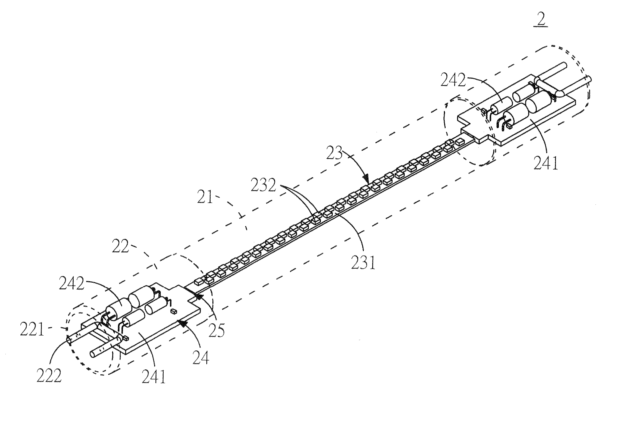
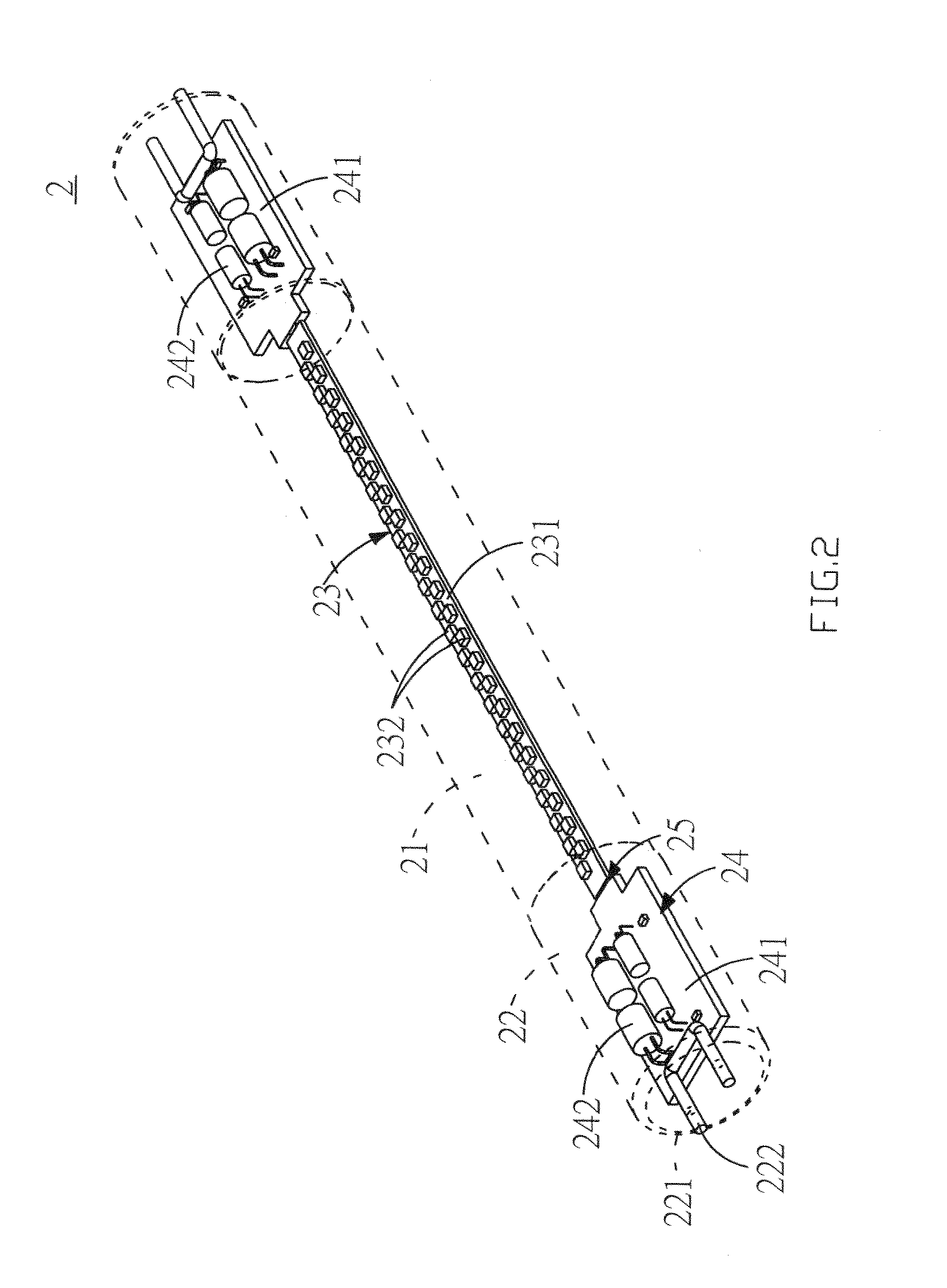
[0023]A lamp tube 2 according to the present invention, as shown in FIG. 2, at least comprises:
[0024]a tube body 21, which can be a light transparent hollow tube body that is assembled on at least one end thereof with a fixed cover 22 being provided thereon with through holes 221 such that electrical connection terminals 222 being fixed and exposed;
[0025]a light-emitting module 23, which is disposed in the tube body 21 and is provided with a first circuit board 231 and a plurality of LEDs 232 disposed on the first circuit board 231;
[0026]a driving module 24, which is disposed in the tube body 21 and is provided with at least a second circuit board 241 and a drive circuit 242 disposed on the second circuit board 241, as shown in the embodiment of this figure, two of the second circuit boards 241 being respectively disposed in the fixed covers 22; and
[0027]electrical connection modules 25, each of which is disposed between the first and second circuit boards 231, 241 and forms an elec...
second embodiment
[0029]FIGS. 4 and 5 show the present invention. The lamp tube is similarly provided with: a tube body 21, a light-emitting module 23, a driving module 24 and electrical connection modules 25. The tube body 21 is provided with a light transparent body 211 and a supporting body 212 which are assembled with each other. A fastening means 26 is disposed between the light transparent body 211 and the supporting body 212. The fastening means 26 can be a projection 261 and a rail 262 that are mutually engageable. The projection 261 is disposed on the light transparent body 211 and the rail 262 is disposed on the supporting body 212 (or the projection is disposed on the supporting body and the rail is disposed on the light transparent body). The light transparent body 211 and the supporting body 212 can be assembled with each other by the engagement of the projection 261 with the rail 262. The supporting body 212 can be provided with a placement portion 213 and a heat sink 214 disposed under...
third embodiment
[0034]The lamp tube 2 can be further cascaded with at least one light-emitting assembly 5 by means of an electrical connection member 4, as shown in FIG. 14. The light-emitting assembly 5 is provided with a tube body 51 and a light-emitting module 52 such that the light-emitting module 23 in the lamp tube and the light-emitting module 52 in the light-emitting assembly can share the drive circuit 242 on one of the second circuit board 241.
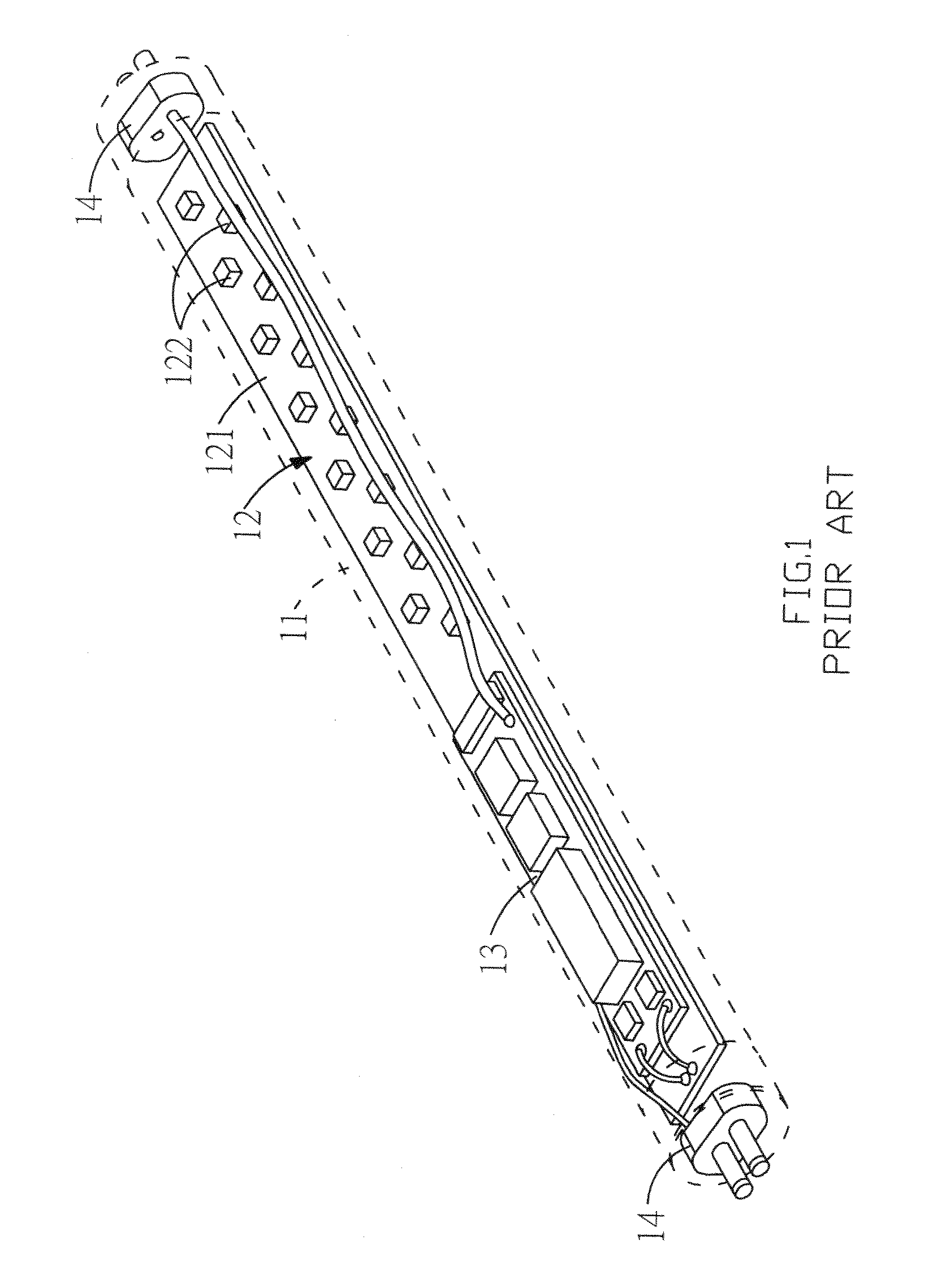
[0035]It deserves to be mentioned that a driving module and a light-emitting module permanently assembled in a prior art lamp tube are manufactured in a separately mountable and demountable manner according to the present invention. This allows the user to independently replace or repair the driving module or the light-emitting module without discarding the entire lamp tube so as to effectively save costs and achieve the effects of energy saving and environmental protection.
PUM
 Abstract
Description
Claims
Application Information
 - R&D
- Intellectual Property
- Life Sciences
- Materials
- Tech Scout
- Unparalleled Data Quality
- Higher Quality Content
- 60% Fewer Hallucinations
Browse by: Latest US Patents, China's latest patents, Technical Efficacy Thesaurus, Application Domain, Technology Topic, Popular Technical Reports.
© 2025 PatSnap. All rights reserved.Legal|Privacy policy|Modern Slavery Act Transparency Statement|Sitemap|About US| Contact US: help@patsnap.com


