Liquid discharge apparatus

a liquid discharge device and liquid discharge technology, applied in printing and other directions, can solve the problems of not being able to avoid the increase in the size and cost of the inkjet printer caused by the motor, and achieve the effects of reducing the size improving the economic efficiency of the inkjet printer, and high cleaning

Inactive Publication Date: 2010-08-12
SONY CORP
View PDF3 Cites 14 Cited by
  • Summary
  • Abstract
  • Description
  • Claims
  • Application Information

AI Technical Summary

Benefits of technology

[0014]However, in each of these techniques, there is provided a special motor to rotate the cleaning roller or the cleaning belt or to wind the cleaning cloth. For this reason, it may not be possible to avoid the increase in the size and cost of the inkjet printer that are caused by the motor.
[0015]Thus, it is desirable to reduce the size of an inkjet printer and to improve the economic efficiency of the inkjet printer while maintaining a high cleaning effect.
[0019]According to the embodiment of the invention, the liquid adsorbent is relatively moved by the moving means, so that the liquid adsorbent adsorbs liquid attached to a portion of the liquid discharge head where the nozzle arrays are formed. Further, the relative movement of the liquid adsorbent is used as a source of power that rotates the rotating shaft of the support roller. When the rotating shaft is rotated in the normal direction, the support roller is rotated by the liquid adsorbent. Accordingly, since an adsorbing portion of the liquid adsorbent is changed, it may be possible to maintain a high cleaning effect. In addition, since it is not necessary that a special motor for rotating the liquid adsorbent is provided, it may be possible to reduce the size of the inkjet printer and to improve the economic efficiency of the inkjet printer.

Problems solved by technology

For this reason, it may not be possible to avoid the increase in the size and cost of the inkjet printer that are caused by the motor.

Method used


Image

  • Liquid discharge apparatus
  • Liquid discharge apparatus
  • Liquid discharge apparatus

Examples


Embodiment Construction

[0035]Embodiments of the invention will be described below with reference to drawings.

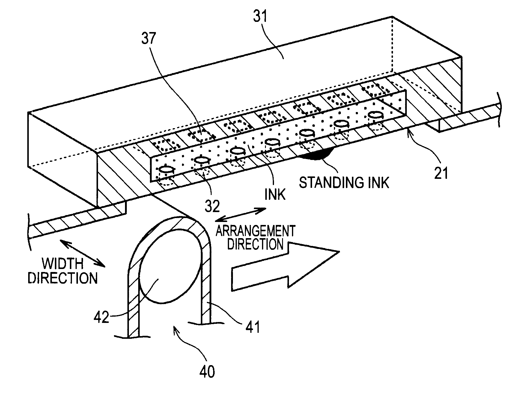
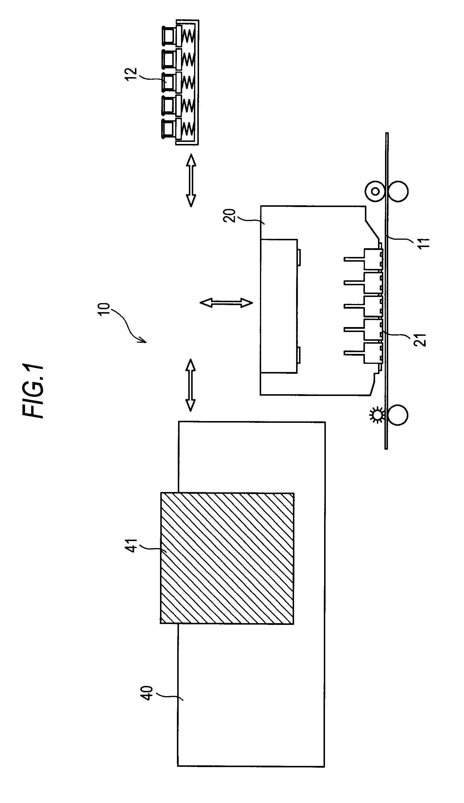
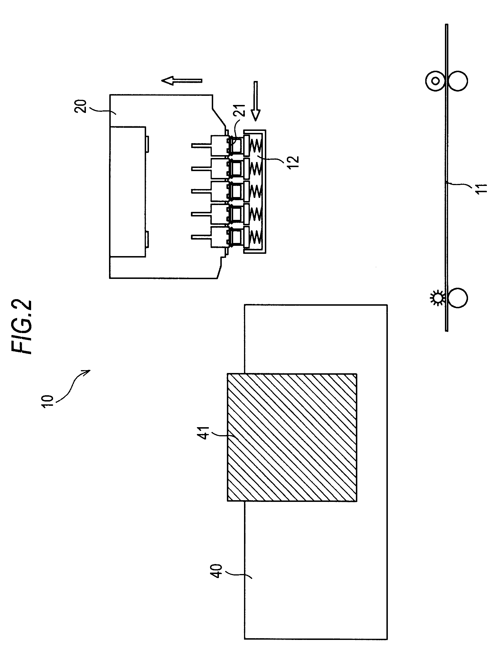
[0036]Here, a liquid discharge apparatus of an embodiment of the invention is an inkjet printer 10, which discharges ink as liquid, in the following embodiments. Further, the inkjet printer 10 is a line inkjet printer that includes a line head 20 (which serves as a liquid discharge head in the invention) corresponding to a printing width (for example, A4 size). Furthermore, a nozzle array 32a, where a plurality of nozzles 32 for discharging ink is arranged in one direction at a predetermined pitch over the length of a printable maximum-size recording sheet (which corresponds to an object to which ink is discharged) in a width direction, is formed at the line head 20. A portion where the nozzle array 32a is formed forms an ink discharge surface 21. In addition, the inkjet printer 10 manages color printing, and includes a nozzle array 32a for each of ink colors, such as yellow (Y), magenta (M), cyan ...


PUM


Abstract

A liquid discharge apparatus includes: nozzles discharging liquid; a liquid discharge head including nozzle arrays where the nozzles are arranged in one direction; a liquid adsorbent adsorbing liquid attached to a portion of the liquid discharge head where the nozzle arrays are formed; a moving means for relatively moving the liquid adsorbent in an arrangement direction of the nozzles; support rollers supporting the liquid adsorbent so as to allow the liquid adsorbent to rotate; a rotating shaft corresponding to the axis of rotation of the support roller and being rotated in a normal or reverse direction by using the relative movement of the liquid adsorbent, which is caused by the moving means, as a source of power; and a reverse rotation preventing means for transmitting the normal rotation of the rotating shaft to the support roller and not transmitting the reverse rotation of the rotating shaft to the support roller.

Description

BACKGROUND OF THE INVENTION[0001]1. Field of the Invention[0002]The present invention relates to a liquid discharge apparatus that can maintain a high cleaning effect when cleaning a liquid discharge head where nozzle arrays for discharging liquid are formed.[0003]2. Description of the Related Art[0004]A liquid discharge apparatus such as an inkjet printer forms an image on a recording sheet by discharging ink from nozzle arrays that are formed at a liquid discharge head. For this reason, if an image is formed while a liquid discharge surface (a portion where the nozzle arrays are formed) of the liquid discharge head is contaminated or liquid or dirt is attached to the liquid discharge surface, printing quality deteriorates. In particular, if ink, which has a color different from the colors of existing ink (liquid), may flow back from nozzles in the case of an inkjet printer that manages full color, the color of the ink is mixed to the colors of the existing ink (liquid), so that mi...

Claims


Application Information

Patent Timeline
Patent Type & Authority Applications(United States)
IPC IPC(8): B41J2/165
CPCB41J2/16585B41J2/16535
Inventor YAMAGUCHI, SHUNJIHIRASHIMA, SHIGEYOSHI
Owner SONY CORP
Why Eureka
Try Eureka