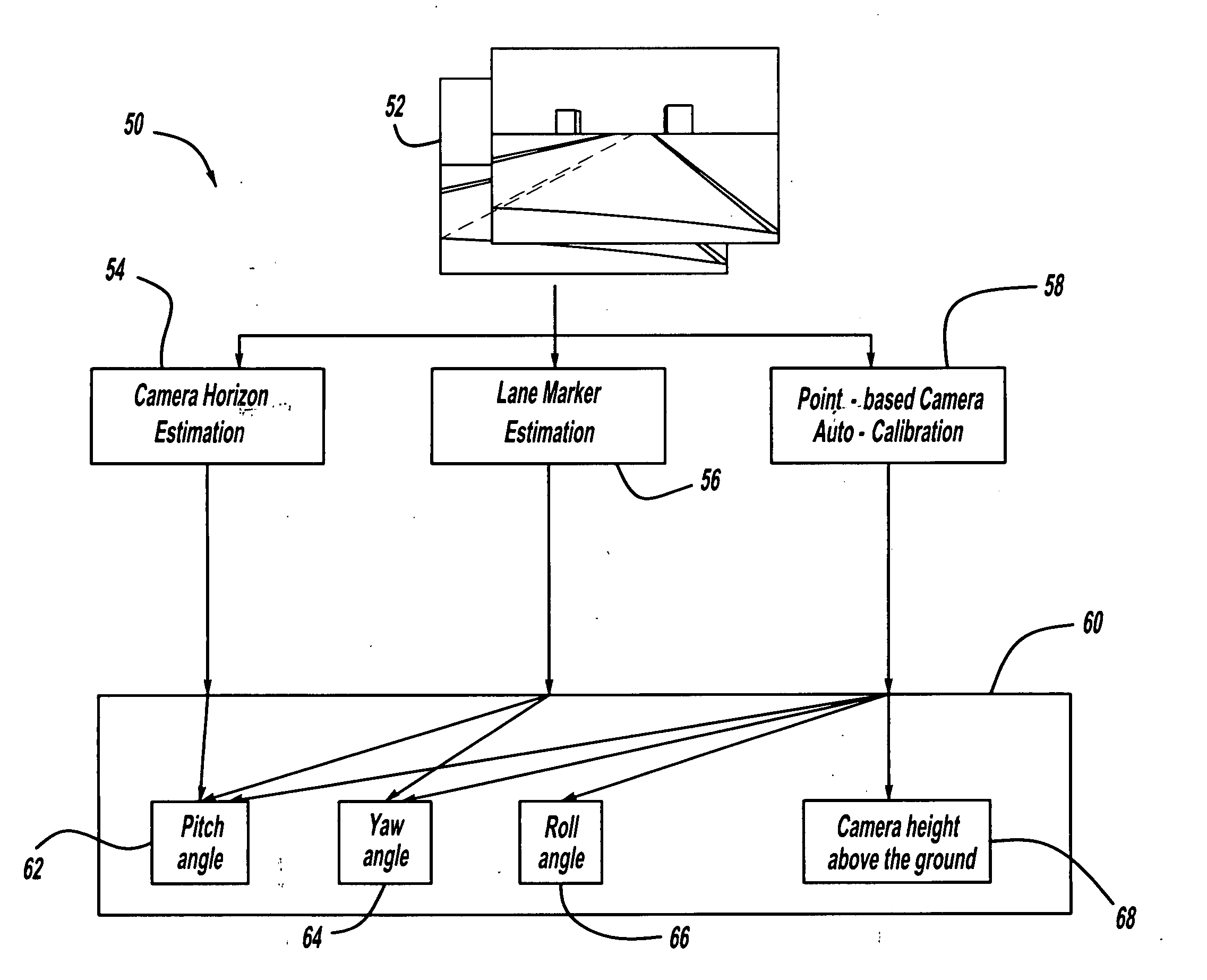
Camera auto-calibration by horizon estimation

a technology of auto-calibration and horizon estimation, applied in the field of camera auto-calibration by horizon estimation, can solve the problems of inaccurate overlaid vehicle trajectory graphics on the camera image, inability of camera systems to provide camera calibration, and inability to provide camera calibration. to achieve the effect of reducing nois

Inactive Publication Date: 2010-08-12
GM GLOBAL TECH OPERATIONS LLC
View PDF1 Cites 51 Cited by
  • Summary
  • Abstract
  • Description
  • Claims
  • Application Information

AI Technical Summary

Benefits of technology

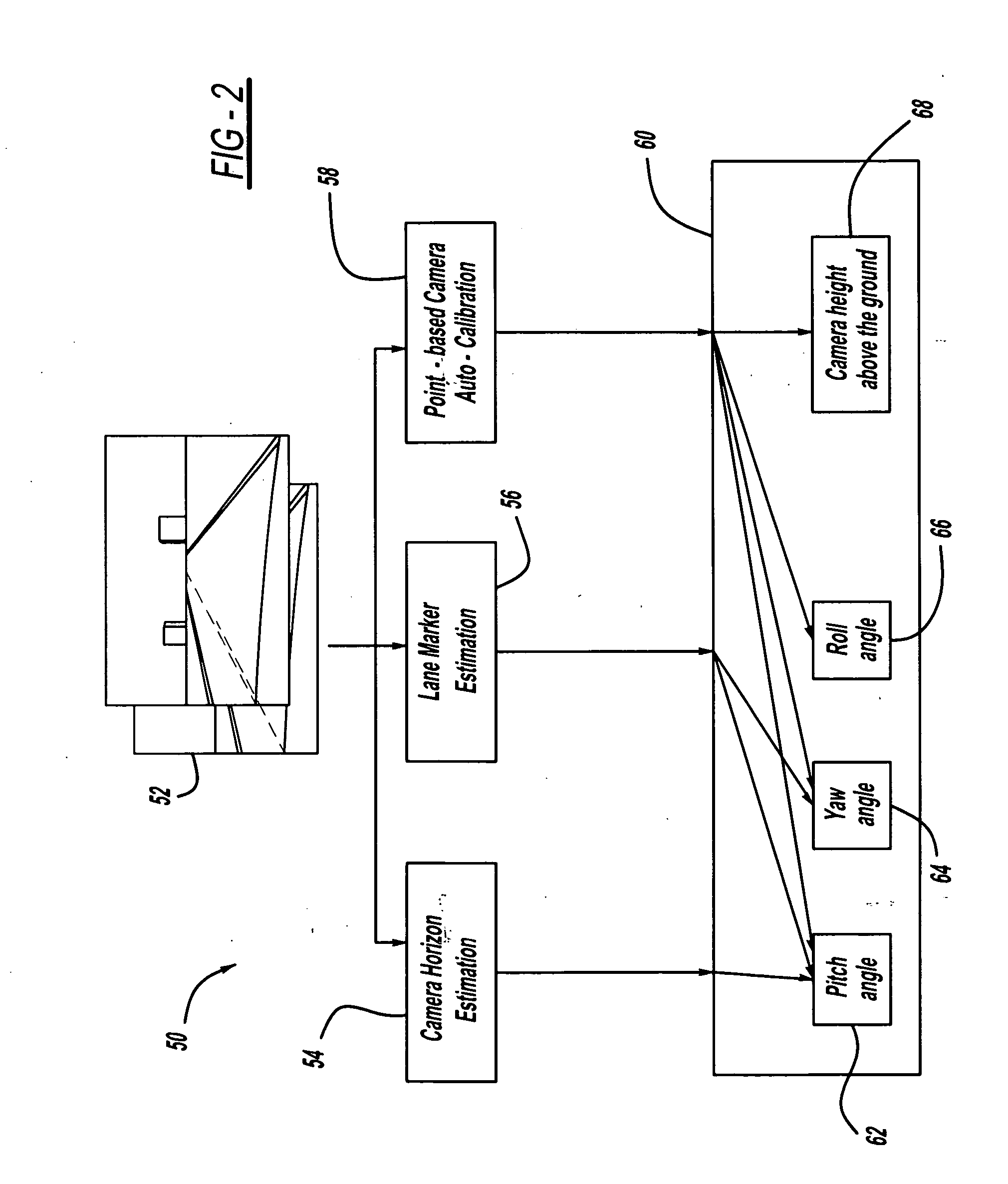
This patent describes a way to estimate the position of the sun or other objects in an image taken by a camera. By analyzing the texture and movement of the image, the system calculates which parts of the image don't change when the camera moves (called static features). These static features are compared to similar ones in another image taken at a different time to determine if they match up. If there is a difference, it indicates how much the camera has moved since its last adjustment. Using this data, the system automatically calibrates the camera to ensure accurate photos are being captured.

Problems solved by technology

The technical problem addressed in this patent is how to accurately calibrate cameras used in modern vehicles for various functions like backup assistance, monitoring driver behavior, and identifying structures along the road. Existing methods often result in errors when trying to align graphic elements onto the camera image, causing difficulty during driving maneuvers. Additionally, current calibration processes require significant amounts of time and resources and cannot easily adapt to changes in the vehicle's configuration or external factors like weather conditions.

Method used


Image

  • Camera auto-calibration by horizon estimation
  • Camera auto-calibration by horizon estimation
  • Camera auto-calibration by horizon estimation

Examples


Embodiment Construction

[0012]The following discussion of the embodiments of the invention directed to a system and method for providing an estimation of the horizon in an image from a camera for camera auto-calibration in the pitch direction is merely exemplary in nature, and is in no way intended to limit the invention or its applications or uses. For example, the present invention has particular application for calibrating a vehicle camera. However, as will be appreciated by those skilled in the art, the present invention will have application for cameras other than vehicle cameras.

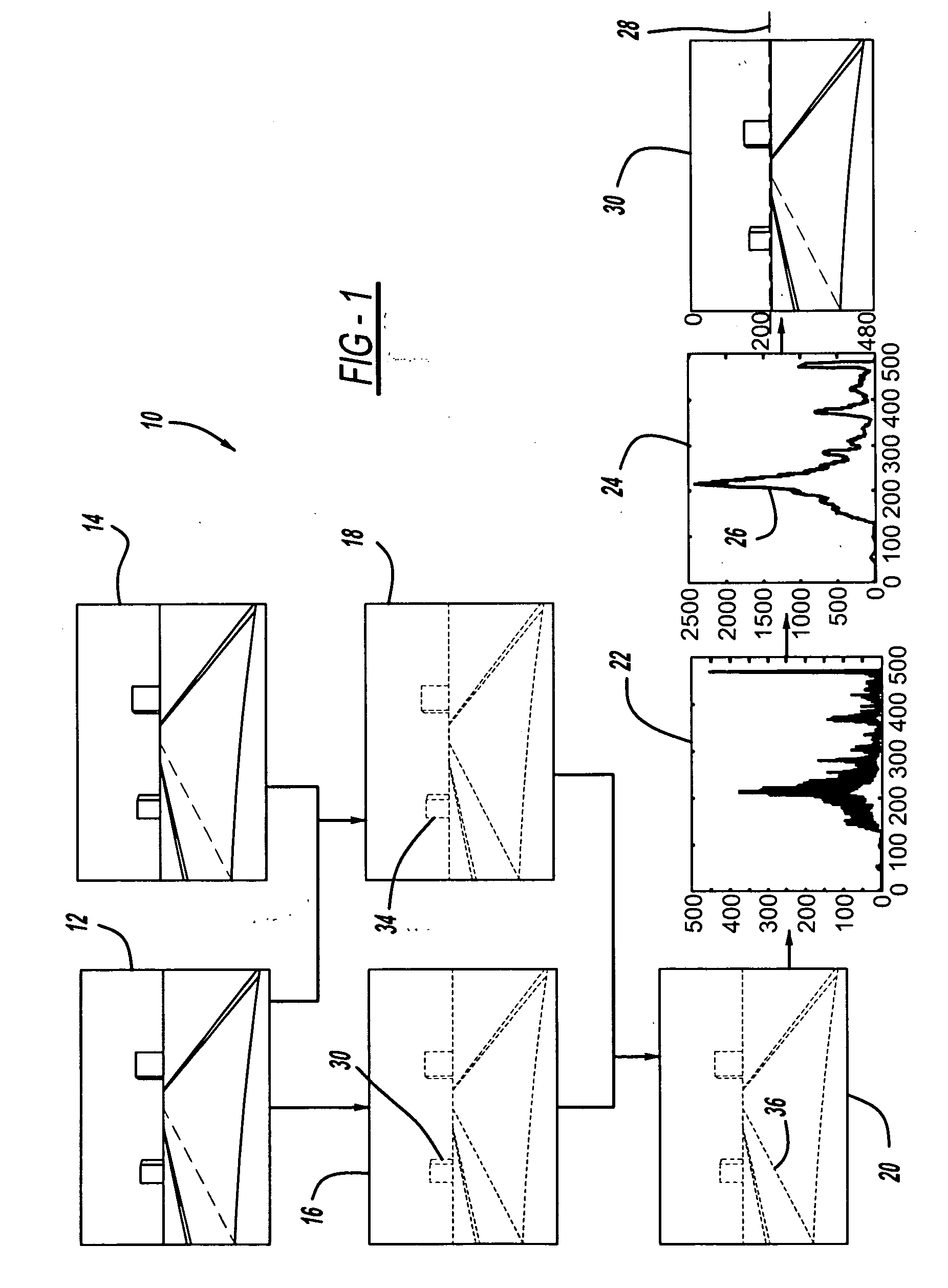
[0013]FIG. 1 is a flow chart diagram 10 showing a method for estimating a horizon in an image of a camera. A camera image 12 is shown at time k and a camera image 14 is shown at time k+1 of a road in front of a vehicle. As will be discussed below, the method estimates the horizon in the images 12 and 14, which is basically a line that contains many horizontal edges where the sky and road intersect. The horizon is basically th...


PUM


Abstract

A method for estimating the horizon in an image of a camera to provide camera auto-calibration in the pitch direction. The method includes taking an image of a scene and generating a texture map of the image using horizontal edge detection analysis to locate horizontal edges in the scene. The method also includes providing a motion map by providing image differencing between subsequent images to find areas in the scene with no motion while the vehicle is moving. The texture map and the motion map are combined to identify the areas in the image that do not move and contain horizontal edges. A horizontal projection is generated from the combined map by counting white dots in the map in the horizontal direction. The horizontal projection is smoothed to eliminate noise and the location of the horizon is estimated in the image by identifying the maximum peak in the horizontal projection.

Description


Claims


Application Information

Patent Timeline
Owner GM GLOBAL TECH OPERATIONS LLC
Why Eureka
Try Eureka