Disk drive device
a technology of a disk drive and a sleeve, which is applied in the field of sleeve devices, can solve the problems of hard disk drive malfunction, magnetic head touching the magnetic recording disk, and disturbing the tracing of the recording track, so as to reduce vibrations
- Summary
- Abstract
- Description
- Claims
- Application Information
AI Technical Summary
Benefits of technology
Problems solved by technology
Method used
Image
Examples
first embodiment
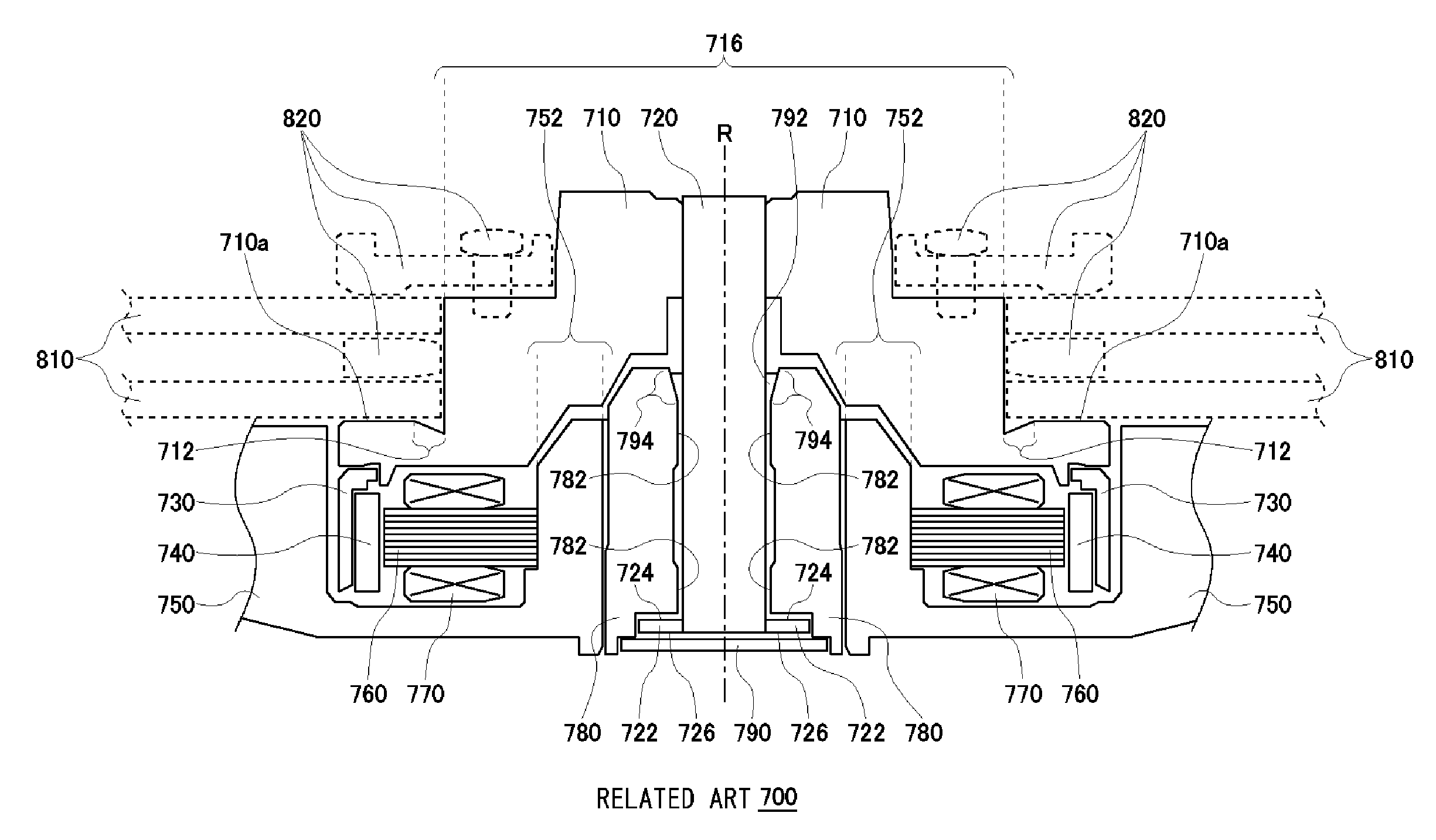
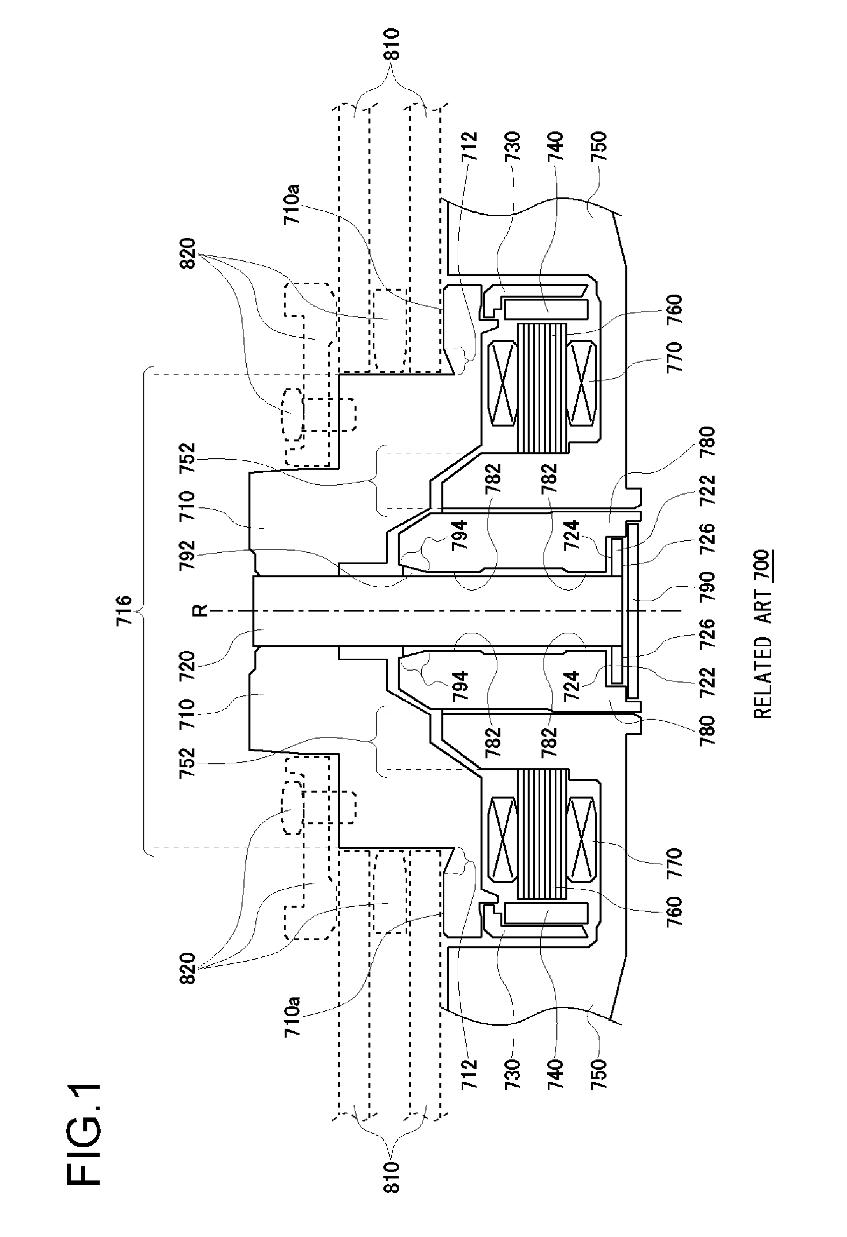
[0046]First, assume that the Eigen frequency F0 of the second order rocking-mode when not rotating is given for the brushless motor according to the present invention. In order to avoid the situation where the one of the three torque-ripple frequencies coincides with either one of the two split frequencies of the resonance, the rotational frequency N (Hz) should satisfy the following condition (Equation 3) when M=3 (three-phase driving):
N<F0 / (3*P+2) (Hz) (Equation 3)
[0047]By way of example, the parameters that may be adopted for the brushless motor according to the first embodiment of the present invention are: the diameter of the mounted magnetic recording disk being 3.5 inches (88.9 mm): the number of magnetic poles of the magnet being 8 (P=8); and the Eigen frequency F0 being 2600 Hz. In this case, the upper limit of the rotational frequency N (Hz) of the motor is determined to be 100 Hz (6000 min−1). In reality, it is preferred that the rotational frequency is set to be 540...
second embodiment
[0054]FIG. 4 is a cross section of a brushless motor 100 according to the present invention. The brushless motor 100 comprises a hub 110, a shaft 120, a flange 122, a cylindrical yoke 130, a cylindrical magnet 140, a base plate 150, a laminated core 160, coils 170, a sleeve 180, a plate 190, and lubricant 192. The laminated core 160 has twelve teeth. Each of the coils 170 is wound around one of the twelve teeth, respectively. A three-phase (M=3) sinusoidal driving current flows through the coils 170.
[0055]The hub 110 is made of a metal, such as Aluminum or Iron. A ring-shaped first groove 110b and a ring-shaped second groove 110c are formed on the inner surface 110a of the hole arranged in the center of the hub 110. The first groove 110b and the second groove 110c are made in order to store glue. The first groove 110b is separated from the second groove 110c in the axial direction. It is preferred that both the depth of the first groove 110b and the depth of the second groove 110c a...
third embodiment
[0073]FIG. 6 is a cross section of a brushless motor 300 according to the present invention. The brushless motor 300 comprises a hub 310, a thrust ring 318, a shaft 120, a cylindrical magnet 340, a base plate 350, a laminated core 360, coils 370, a sleeve 380, a plate 390, and lubricant 392. A magnetic recording disk 810 is mounted on the brushless motor 300 by a locking means 820. The hub 310 has a radial concave portion 312. The hub 310 has a cylindrical hanging portion 316 that has a hanging-shape from the lower surface of the hub 310. The thrust ring 318 is fixed on the inner surface of the hanging portion 316.
[0074]A pair of herringbone-shaped radial dynamic pressure grooves 382 and 384, which are separated from each other, are formed on the inner surface of the sleeve 380. The lower one of the radial dynamic pressure grooves is referred to as a first radial dynamic pressure groove 382, and the upper one is referred to as a second radial dynamic pressure groove 384. A herringbo...
PUM
 Abstract
Description
Claims
Application Information
 - R&D
- Intellectual Property
- Life Sciences
- Materials
- Tech Scout
- Unparalleled Data Quality
- Higher Quality Content
- 60% Fewer Hallucinations
Browse by: Latest US Patents, China's latest patents, Technical Efficacy Thesaurus, Application Domain, Technology Topic, Popular Technical Reports.
© 2025 PatSnap. All rights reserved.Legal|Privacy policy|Modern Slavery Act Transparency Statement|Sitemap|About US| Contact US: help@patsnap.com


