
Fuel nozzle having aerodynamically shaped helical turning vanes

Active Publication Date: 2010-08-19
ROLLS ROYCE PLC
View PDF8 Cites 29 Cited by
  • Summary
  • Abstract
  • Description
  • Claims
  • Application Information

AI Technical Summary

Benefits of technology

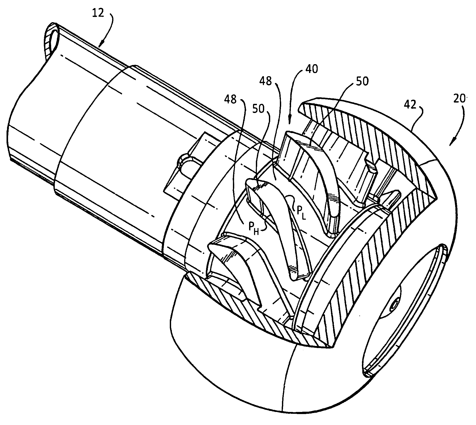
[0012]Each vane has a maximum normal thickness associated with the transitional vane section. In one embodiment of the subject invention, the normal vane thickness changes or otherwise decreases from the transitional vane section to the trailing edge surface of the vane. Preferably, the normal vane thickness also changes or otherwise decreases from the transitional vane section to the leading edge surface of the vane. However, it is envisioned that the lead-in vane section that extends from the leading edge to the transitional vane section could have a constant vane thickness. It is also envisioned that any axial vane segment along the axial extent of the vane could have a constant vane thickness. In any case, the resulting airfoil shaped helical vanes of the subject invention function to effectively impart a high degree of swirl while minimizing the risk of separation.

Problems solved by technology

However, when a higher swirl factor was desired for certain engine application, there was a tendency for the air flow to separate from the helical vanes.
This was generally associated with a reduction in the effectiveness of the geometric flow area of the nozzle.

Method used


Image

  • Fuel nozzle having aerodynamically shaped helical turning vanes
  • Fuel nozzle having aerodynamically shaped helical turning vanes
  • Fuel nozzle having aerodynamically shaped helical turning vanes

Examples


Embodiment Construction

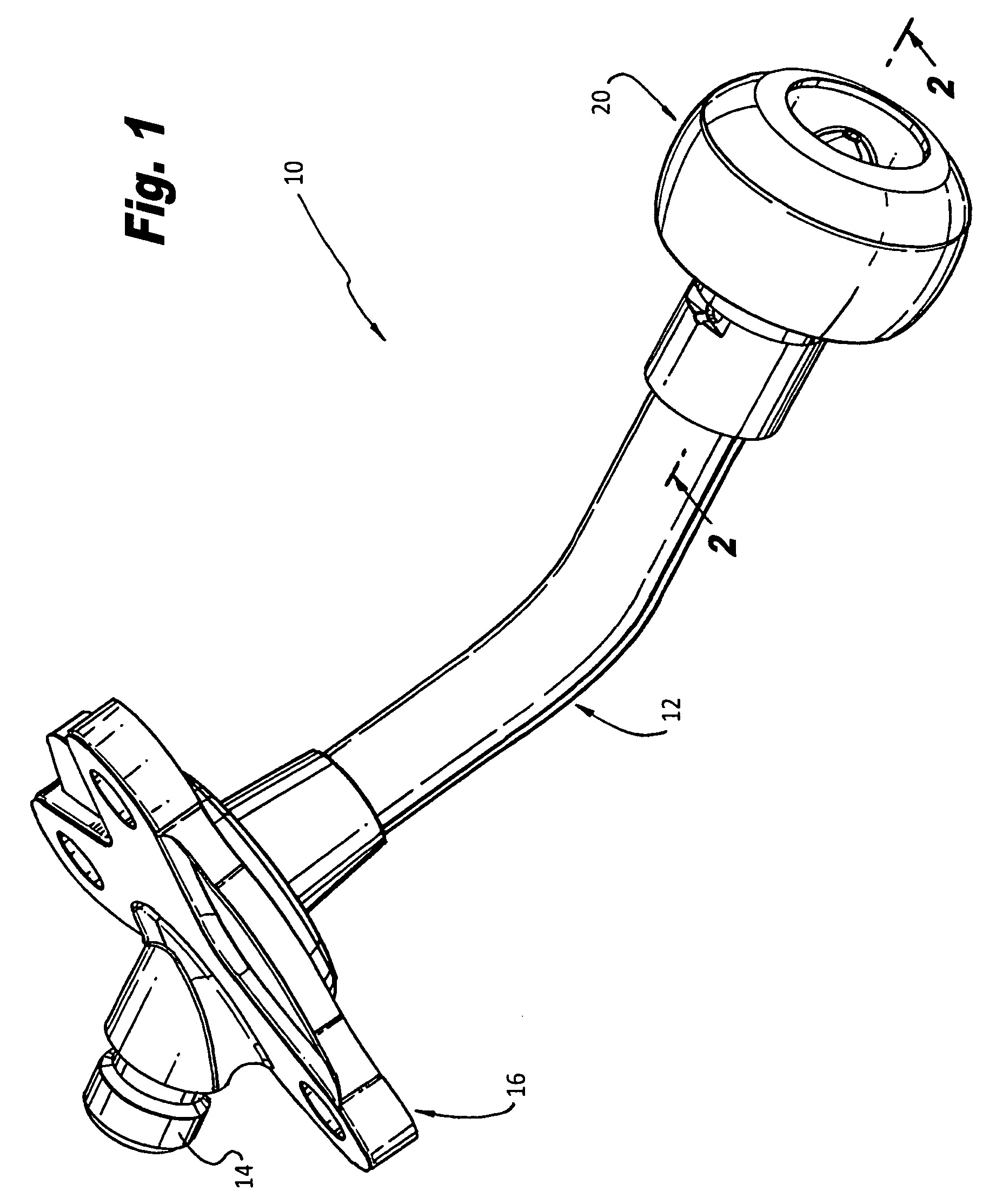
[0020]Referring now to the drawings, wherein like reference numerals identify or otherwise refer to similar structural features or elements of the various embodiments of the subject invention, there is illustrated in FIG. 1 a fuel injector for a gas turbine engine. Fuel injector 10 includes an elongated feed arm 12 having an inlet portion 14 for receiving fuel, a mounting flange 16 for securing the fuel injector 10 to the casing of a gas turbine engine, and a nozzle assembly 20 at the lower end of the feed arm 12 for issuing atomized fuel into the combustion chamber of a gas turbine engine.

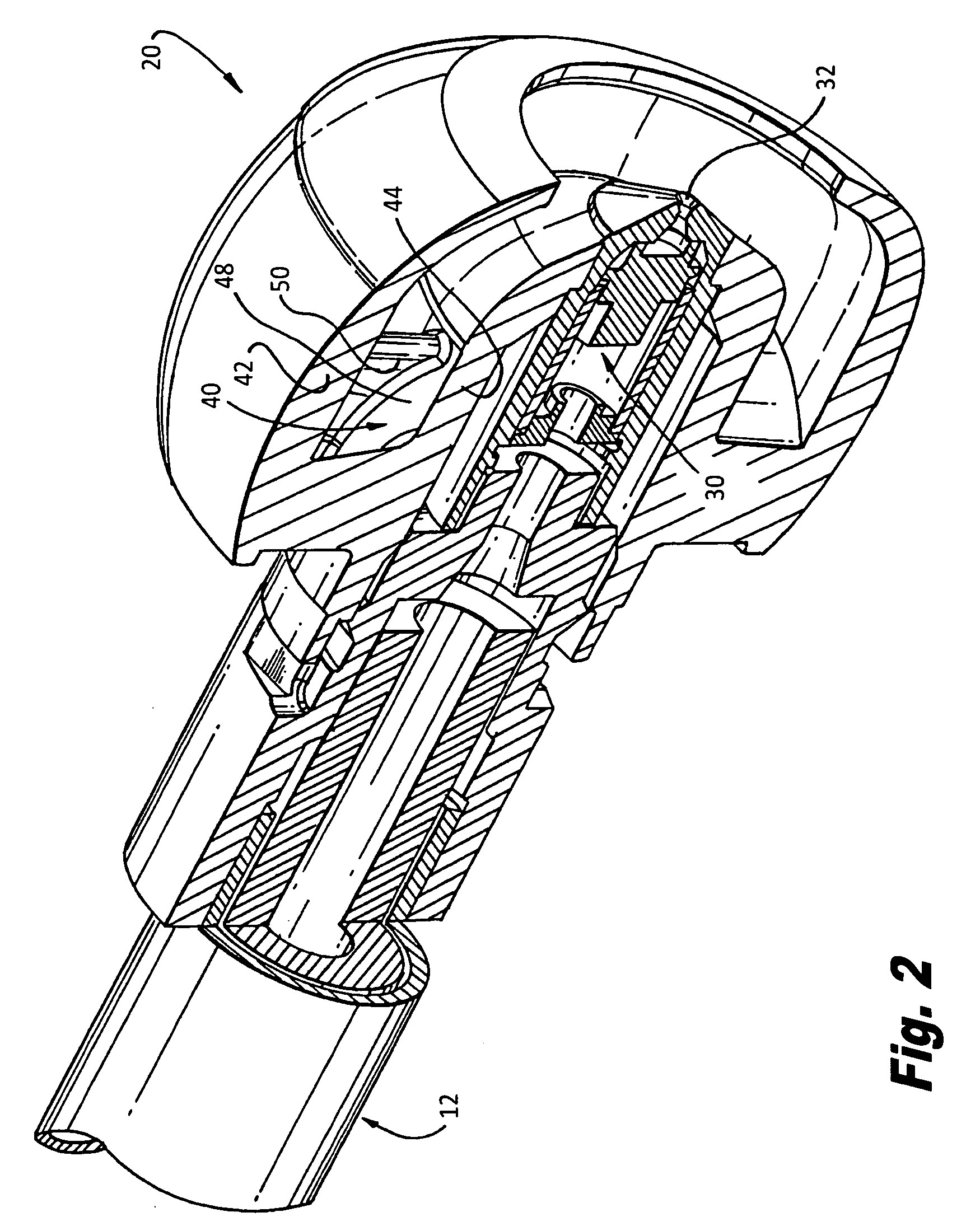
[0021]Referring to FIG. 2, the nozzle assembly 20 of fuel injector 10 includes, among other things, an on-axis fuel circuit 30 and an outer air swirler 40 located radially outward of the fuel circuit 30. The axial fuel circuit 30 issues fuel from an exit orifice 32. The air swirler 40 is bounded by an outer air cap 42 and an inner hub 44. Air swirler 40 includes a plurality of circumferentially di...


PUM


Abstract

A fuel nozzle for a gas turbine engine is disclosed which includes a nozzle body having a longitudinal axis, an elongated annular air passage defined within the nozzle body, and a plurality of circumferentially spaced apart axially extending swirl vanes disposed within the annular air passage, wherein each swirl vane has multiple joined leads and a variable thickness along the axial extent thereof.

Description

BACKGROUND OF THE INVENTION[0001]1. Field of the Invention[0002]The subject invention is directed to fuel nozzles for gas turbine engines, and more particularly, to an air swirler for fuel nozzles having aerodynamically shaped helical turning vanes for efficiently turning the air flow passing through the swirler while minimizing the risk of separation.[0003]2. Description of Related Art[0004]In a fuel nozzle for a gas turbine engine, compressor discharge air is used to atomize liquid fuel. More particularly, the air provides a mechanism to breakup a fuel sheet into a finely dispersed spray that is introduced into the combustion chamber of an engine. Quite often the air is directed through a duct that serves to turn or impart swirl to the air. This swirling air flow acts to stabilize the combustion reaction.[0005]There are many ways to develop swirl in a fuel nozzle. Historically, helical vanes were used because of their ability to effectively turn the air flow. These vanes generated...

Claims


Application Information

Patent Timeline
IPC IPC(8): F02C7/22
CPCF23D11/107F23R3/28F23R3/14
Inventor WILLIAMS, BRANDON PHILIPTHOMPSON, KEVIN EUGENEFOGARTY, ROBERT RUSSELL
Owner ROLLS ROYCE PLC
Learn More