Apparatus for measuring components of a point force

a technology of point force and apparatus, applied in the direction of apparatus for force/torque/work measurement, tension measurement, measurement device, etc., can solve the problem of extremely difficult to obtain such measurements when using known techniques

Inactive Publication Date: 2010-08-19
NEXENSE
View PDF5 Cites 8 Cited by
  • Summary
  • Abstract
  • Description
  • Claims
  • Application Information

AI Technical Summary

Benefits of technology

[0004]An object of the present invention is to provide apparatus for measuring components of a point force, which apparatus can be implemented in a relatively compact form making it particularly suitable for implanted orthopedic devices, but also suitable for many other applications.

Problems solved by technology

Obtaining such measurements is extremely difficult when using known techniques, particularly where the measurements are to be made with respect to implanted orthopedic devices such as described in the above two prior art publications.

Method used


Image

  • Apparatus for measuring components of a point force
  • Apparatus for measuring components of a point force
  • Apparatus for measuring components of a point force

Examples


Embodiment Construction

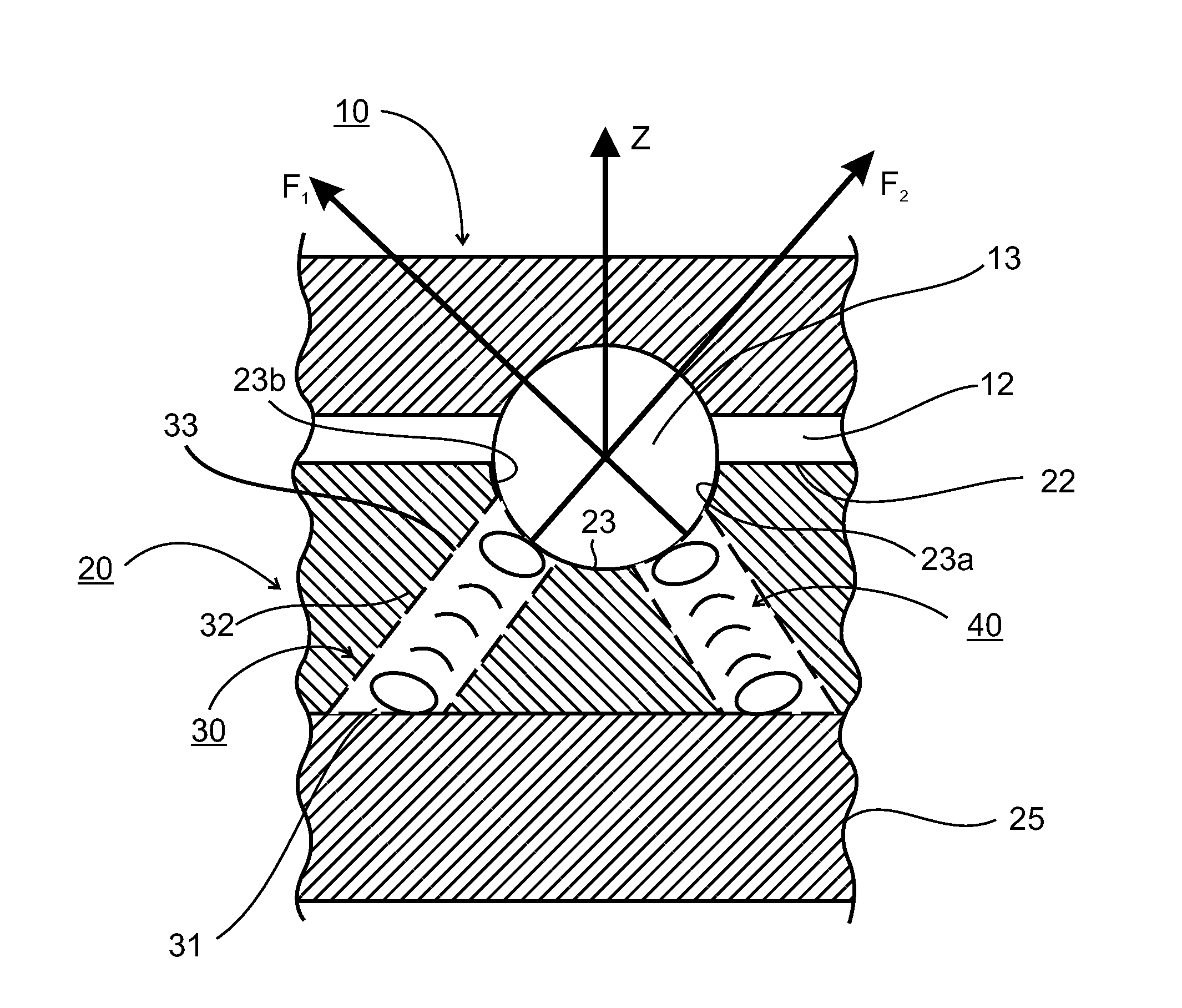
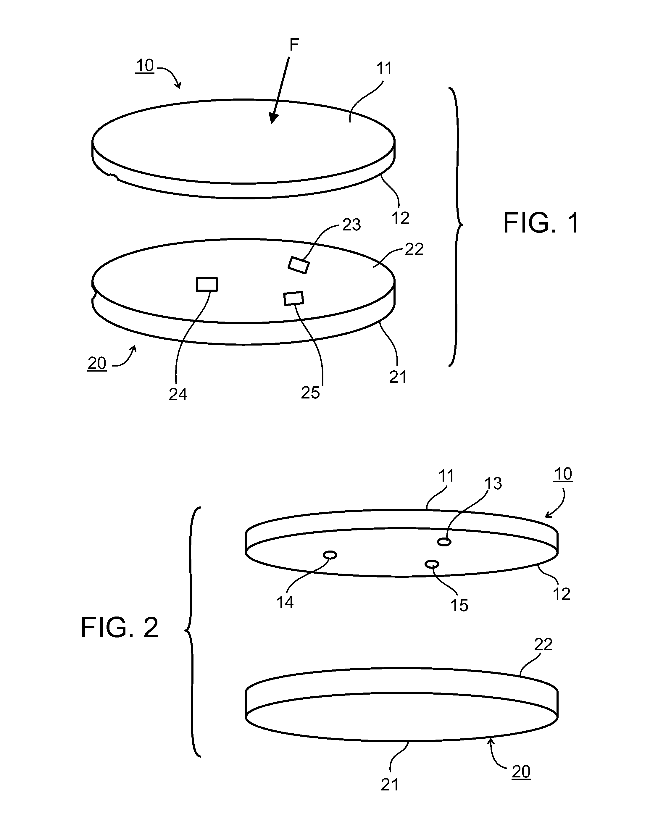
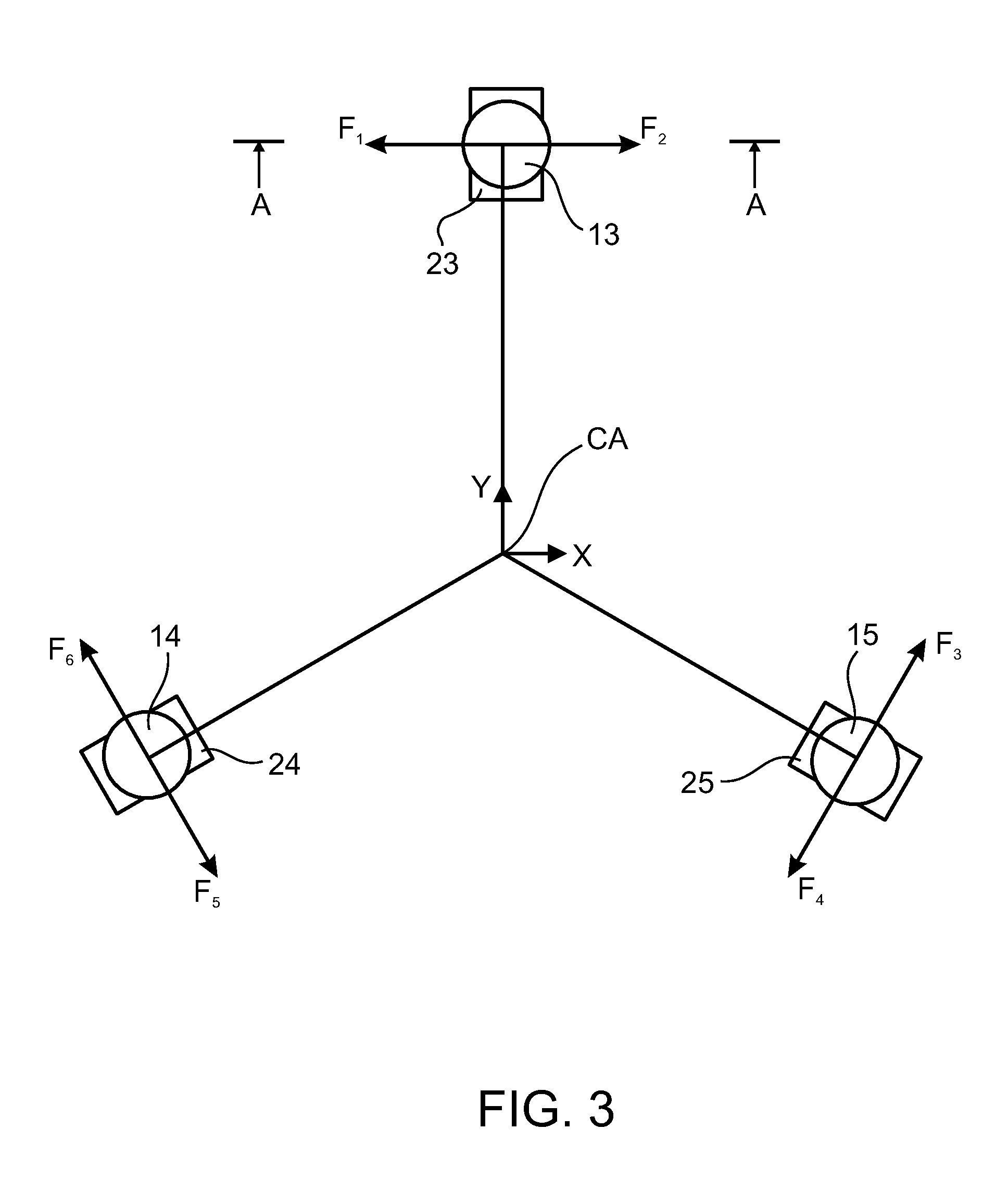
[0014]The preferred embodiment of the invention described below is based on building a mechanical loading system which will transform a force applied to the upper surface of the loading system, represented by a force point vector, into measurable forces at a plurality of support points on the lower surface of the loading system. For this purpose, the upper surface receiving the applied force, represented as a linear vector, is on a first rigid member supported at a plurality of points on its lower surface over a second rigid member, such that the number of unknown forces to be measured is equal to the number of independent equilibrium conditions. The applied force will thus generate, in the underlying rigid member, constraint forces which may be calculated on the basis of six equilibrium conditions without using additional information of body rigidity.

[0015]The pressure distribution of the applied force may be represented by a single force vector applied at a particular location and...


PUM

PropertyMeasurementUnit
forceaaaaaaaaaa
spherical forceaaaaaaaaaa
horizontal distanceaaaaaaaaaa

Abstract

Apparatus for measuring components of a point force includes a first rigid member having an outer surface to receive the point force to be measured, and three spherical force transmitting elements, each of spherical or partial-spherical configuration, projecting from its inner surface, and a second rigid member having an inner surface facing the inner surface of the first member and formed with three sockets for receiving the three spherical force transmitting elements, each of the sockets includes two planar walls diverging in the direction towards the inner surface of the second member so as to be engaged by the respective spherical force transmitting element of the first member at two contact points, and to space apart the inner surfaces of the first and second members. A force sensor is located at each of the two contact points of each of the spherical force transmitting elements to sense the force applied by the respective spherical force transmitting element to each of the two planar surfaces of the second member.

Description

RELATED APPLICATION / S[0001]This application claims the benefit of priority of U.S. Provisional Patent Application No. 61 / 153,661, filed on Feb. 19, 2009, the contents of which are incorporated herein by reference.FIELD AND BACKGROUND OF THE INVENTION[0002]The present invention relates to apparatus for measuring components of a point force, and particularly the magnitude of the point force along the x, y and z axes, respectively, as well as the location of the point force with respect to the x and y axes.[0003]There are many applications where it is necessary or desirable to measure the various components of a force applied at a point to determine the magnitude of the force along each of the X, Y and Z axes, as well as the location of the applied force with respect to the X and Y axes. As an example, such measurements are frequently necessary or desired with respect to implanted orthopedic sensors, such as described in U.S. Pat. No. 6,447,448, assigned to Ball Semiconductor, Inc., or...

Claims


Application Information

Patent Timeline
Patent Type & Authority Applications(United States)
IPC IPC(8): G01L5/00
CPCG01L5/16G01L1/255G01L5/173
Inventor ARIAV, ARIERAVITCH, VLADIMIR
Owner NEXENSE
Why Eureka
Try Eureka