Punching press

Inactive Publication Date: 2010-08-19
BRUDERER ARBON SCHWEIZ
View PDF6 Cites 8 Cited by
  • Summary
  • Abstract
  • Description
  • Claims
  • Application Information

AI Technical Summary

Benefits of technology

[0035]Also it is preferred in this case that the respective lever at its second end is connected via a lug with the tension column. By means of this, the advantage is arrived at that substantially only vertical forces can be transferred via this pivoting point.
[0036]Furthermore, it is preferred in this embodiment of the punching press that a guide is present in each case by means of which the end of the connecting rod, which is remote from the crankshaft, is vertically guided in such a manner that this end is exclusively movable in vertical direction. The end of the connecting rod which end is remote from the crankshaft and in this way is made immobile in horizontal direction, is via a lug connected with the first end of the at least one lever. Through this, the linkage of two levers, which are lying opposite to each other in a mirror-inversed manner and are horizontally immobile, to a common connecting rod becomes possible.
[0037]Accordingly, it is preferred that the end of the respective connecting rod which is remote to the crankshaft is hinged, via separate lugs, to the first ends of two levers which are opposite to each other, are immobile in horizontal direction and, seen in longitudinal direction of the cranks shaft, are arranged in an mirror-inverted manner, which preferably, seen in longitudinal direction of the crankshaft, are dedicated in an mirror-inverted manner in each case to a tension column. By means of this, the advantage of a compact design and of a necessarily synchronous driving of two tension columns is a

Problems solved by technology

A significant bending load of the tension columns is in this construction only possible in case the interconnection between the press ram and the tension column is reali

Method used


Image

  • Punching press
  • Punching press
  • Punching press

Examples


Example

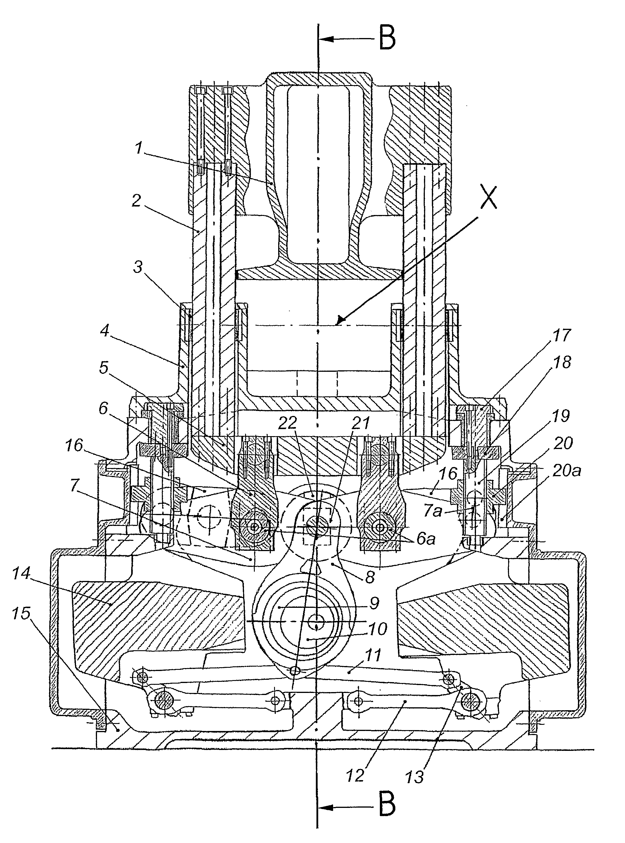
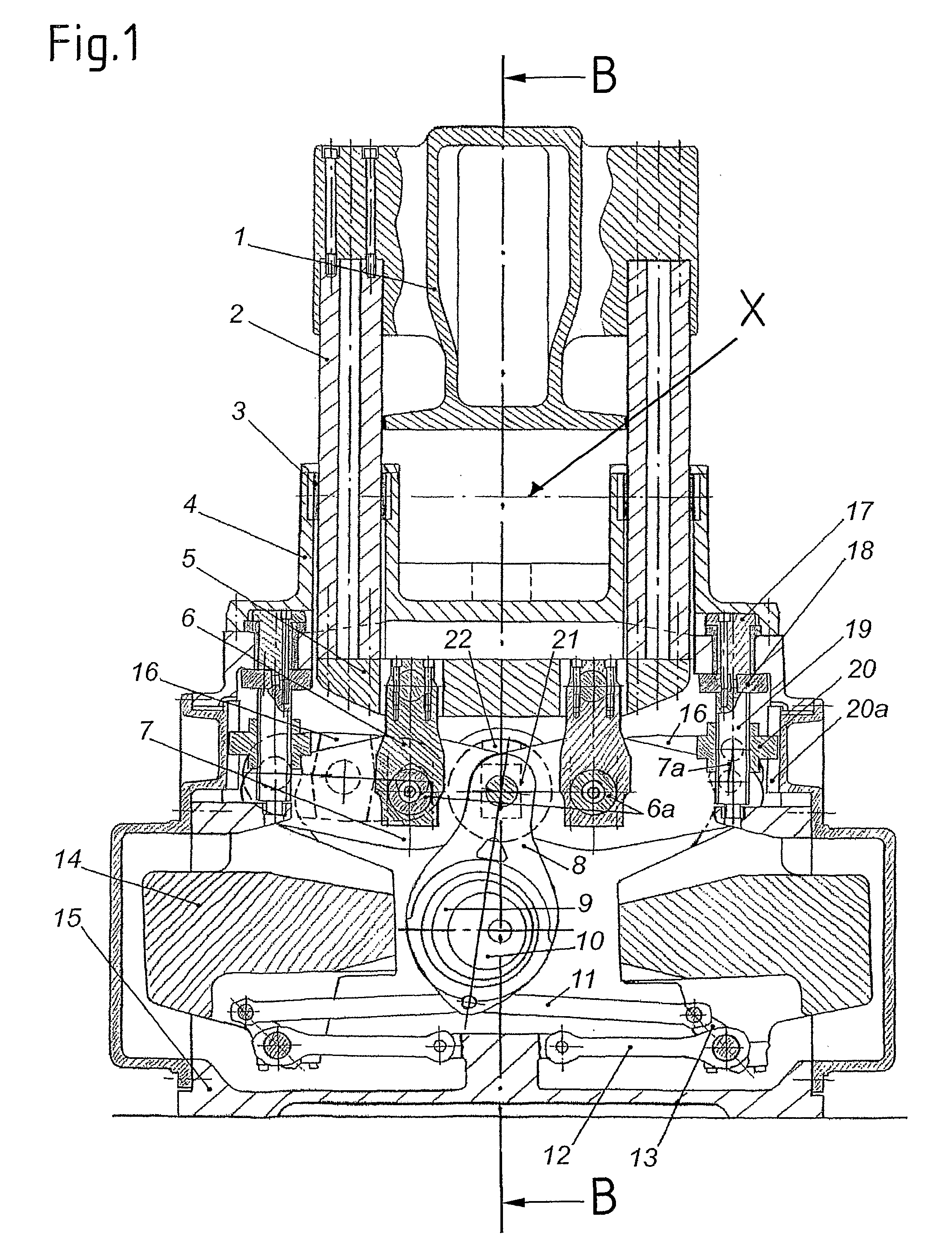
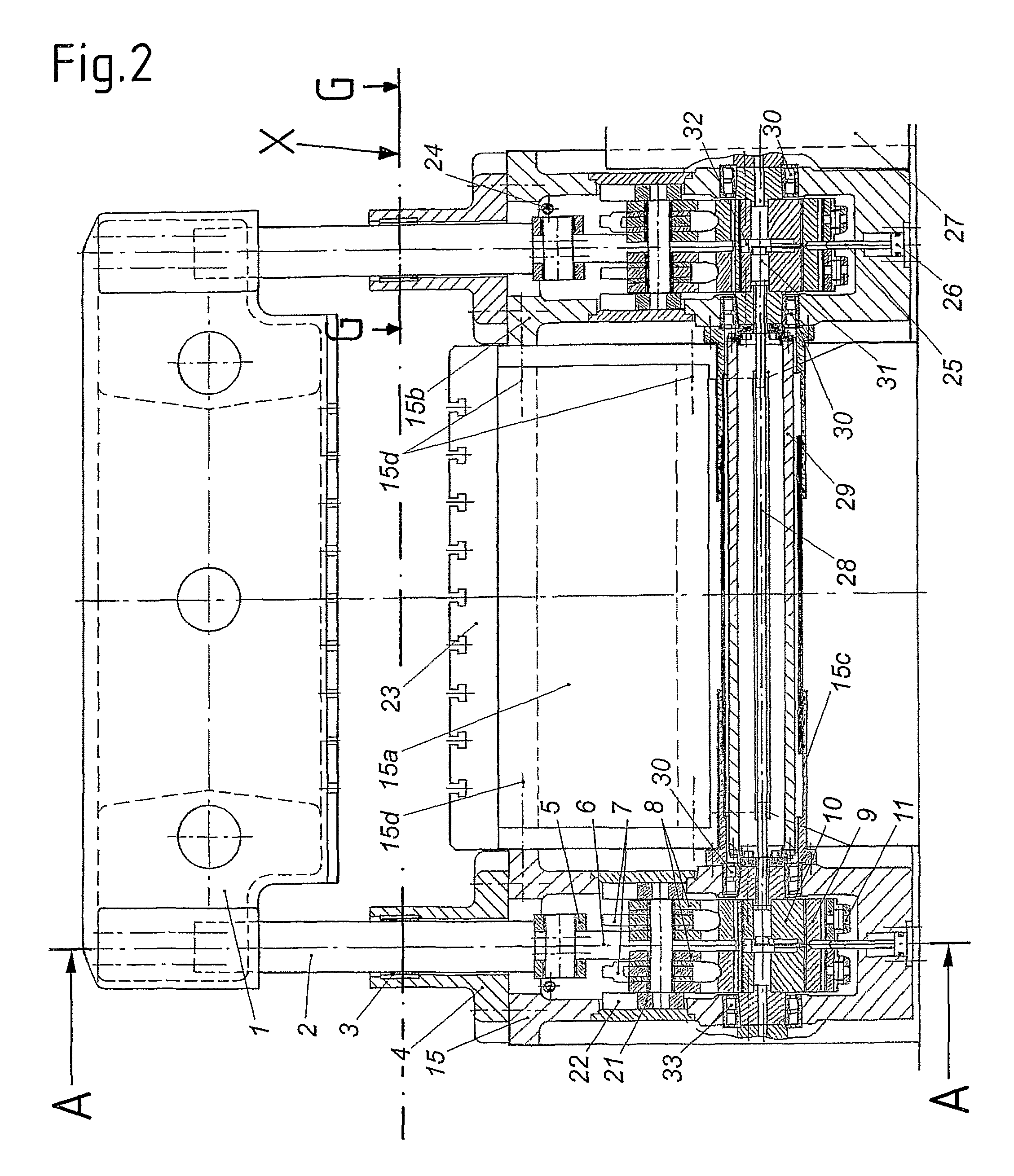
[0054]The basic configuration of a first punching press according to the invention is evident from the FIGS. 1 to 4, which show a cross section (FIG. 1), a longitudinal section (FIG. 2) and horizontal sections through one of the machine housings (FIG. 4) of the punching press, as well as a top view onto the punching press with the press ram removed (FIG. 3).

[0055]As can be seen, the basic structure of the punching press consists of two machine housings 15, 15b, and one cross-member 15a with a clamping plate 23, which by means of screws 15d are interconnected with each other. Above the clamping plate 23 there is arranged a press ram 1, which is rigidly connected with four tension columns 2 that are in each case arranged at its outer corners. Every two of the tension columns 2 in each case are dedicated to one of the two machine housings 15, 15b, which in each case also contain the drive mechanism for the respective tension columns 2 which is described in the following, and are suppor...


PUM


Abstract

The invention relates to a punching press with a clamping plate (27) and with a press ram (1) which lies opposite the upper side of the clamping plate (27) and operates towards the clamping plate (27) and is moveable up and down via four tension columns (2) by means of a crank drive arranged below the belt movement plane (X) of the punching press. The press ram (1) is guided exclusively via the tension columns (2) which, in turn, are guided in inclination-tolerant guides (3) in the belt movement plane (X) in such a manner that the press ram (1) and the tension columns (2) can be positioned obliquely as a consequence of differing longitudinal expansion of the tension columns (2) under an eccentric load by the tension columns (2) being inclined about axes of inclination running in the region of the belt movement plane (X) of the punching press. By means of the configuration according to the invention, distortion of the punching press under an eccentric load, which would lead to uncontrollable operating conditions during the punching and a high degree of wear at the guides of the machine, is avoided, and it can be ensured that, in the event of a possible skewed position of the ram, no tool offset, which would result in a high degree of tool wear or even in tool fracture, occurs.

Description

REFERENCE TO RELATED APPLICATIONS[0001]This application claims the priority of the European Patent Application No. 07 012 661.0, which has been filed on Jun. 28, 2007 and the disclosure of which in its entirety is incorporated in this application by reference.[0002]1. Technical Field[0003]The present invention relates to a punching press according to the preamble of claim 1.[0004]2. Background Art[0005]In the industrial manufacturing of sophisticated punching parts punching presses with a drive mechanism that is arranged below the punching plane and is connected with the press ram via tension columns have proven particularly well suited, since with such punching presses, in particular in embodiments in which the press ram is connected at each of its four outer corners with a tension column, an as high as possible resistance against tilting in the direction of the material flow as well as in the direction transverse thereto can be achieved. As an example for such a press the automati...

Claims


Application Information

Patent Timeline
IPC IPC(8): B30B1/28B30B15/04
CPCB30B1/06B30B15/041B30B15/0029B30B1/263
Inventor HAFNER, JOSEF THOMASDE SANTIS, UGO
Owner BRUDERER ARBON SCHWEIZ
Why Eureka
Try Eureka