Punching press

a technology of punching press and press body, which is applied in the direction of presses, presses, manufacturing tools, etc., can solve the problem of unproblematic bending load

Inactive Publication Date: 2014-06-03
BRUDERER ARBON SCHWEIZ
View PDF43 Cites 3 Cited by
  • Summary
  • Abstract
  • Description
  • Claims
  • Application Information

AI Technical Summary

Benefits of technology

[0010]By means of the configuration according to the invention, a distortion of the punching press under an eccentric load, which would lead to uncontrollable operating conditions and increased wear and tear, is avoided. A significant bending load of the tension columns is in this construction only possible in case the interconnection between the press ram and the tension column is realized in a flexurally rigid manner and is furthermore limited to the transition point between the tension column and the press ram where this bending load is unproblematic. Furthermore, through the configuration according to the invention it is ensured that, in the event of an inclination of the ram, no tool offset, which would result in a high degree of tool wear or even in tool fracture, occurs. Accordingly, through the invention it becomes possible to provide punching presses which combine a minimum of wear and tear, at the machine side as well as at the tool side, with a maximum of punching precision also at eccentric load.
[0042]Such solutions are well proven, cost effective and safe, and furthermore allow for an automated setting / adjusting of the pivoting point via a control system.

Problems solved by technology

A significant bending load of the tension columns is in this construction only possible in case the interconnection between the press ram and the tension column is realized in a flexurally rigid manner and is furthermore limited to the transition point between the tension column and the press ram where this bending load is unproblematic.

Method used


Image

  • Punching press
  • Punching press
  • Punching press

Examples


Embodiment Construction

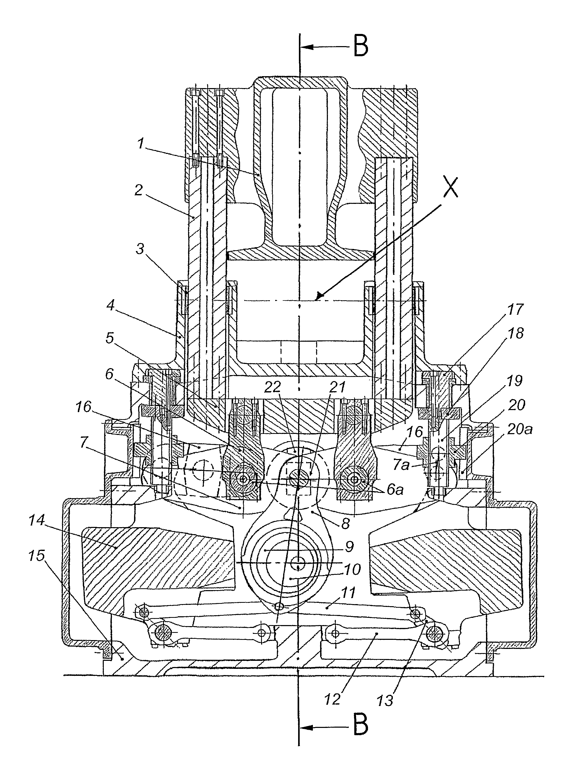
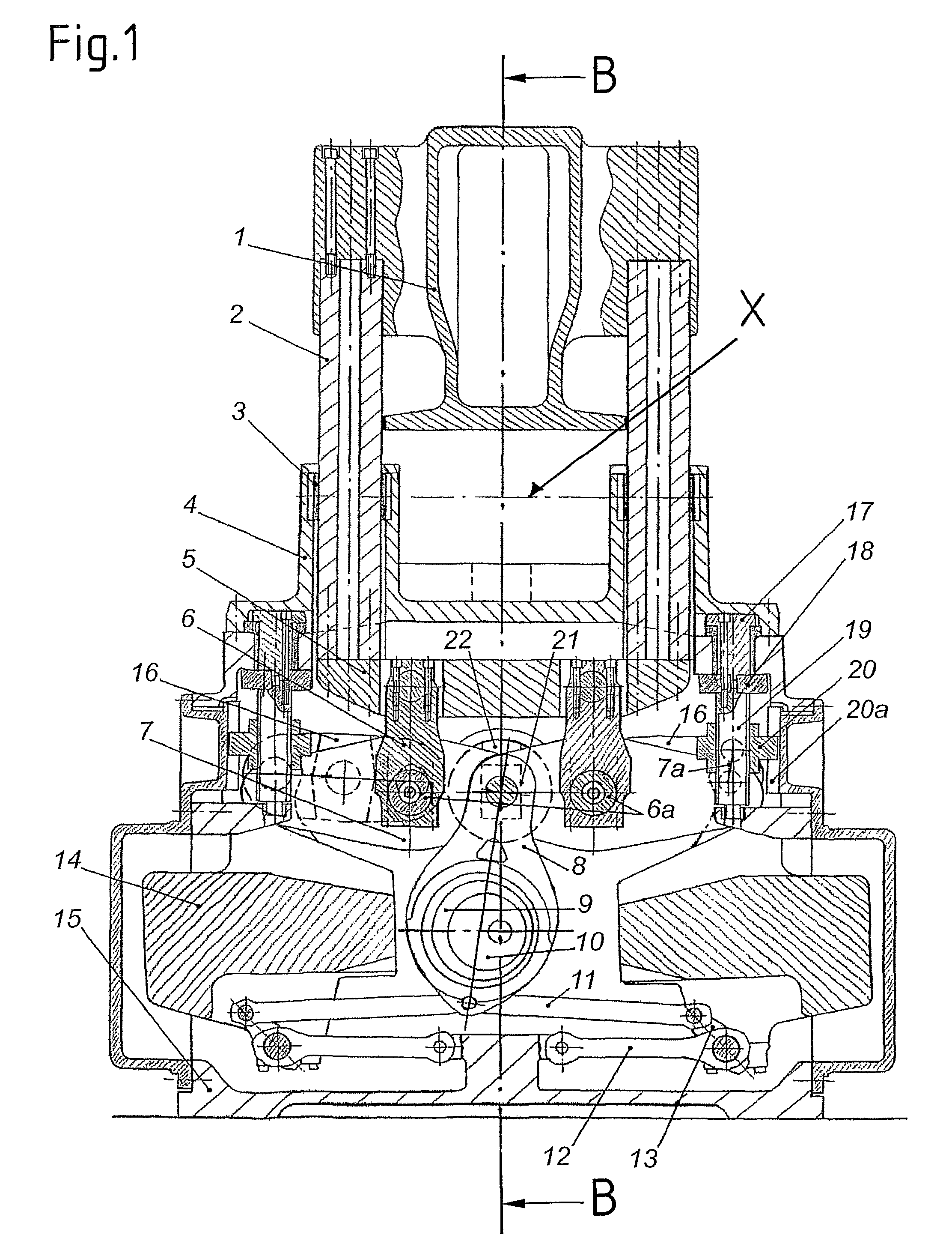
[0054]The basic configuration of a first punching press according to the invention is evident from the FIGS. 1 to 4, which show a cross section (FIG. 1), a longitudinal section (FIG. 2) and horizontal sections through one of the machine housings (FIG. 4) of the punching press, as well as a top view onto the punching press with the press ram removed (FIG. 3).

[0055]As can be seen, the basic structure of the punching press consists of two machine housings 15, 15b, and one cross-member 15a with a clamping plate 23, which by means of screws 15d are interconnected with each other. Above the clamping plate 23 there is arranged a press ram 1, which is rigidly connected with four tension columns 2 that are in each case arranged at its outer corners. Every two of the tension columns 2 in each case are dedicated to one of the two machine housings 15, 15b, which in each case also contain the drive mechanism for the respective tension columns 2 which is described in the following, and are suppor...


PUM

PropertyMeasurementUnit
tensionaaaaaaaaaa
axial forcesaaaaaaaaaa
resistanceaaaaaaaaaa

Abstract

The invention relates to a punching press with a clamping plate (27) and with a press ram (1) which lies opposite the upper side of the clamping plate (27) and operates towards the clamping plate (27) and is moveable up and down via four tension columns (2) by means of a crank drive arranged below the belt movement plane (X) of the punching press. The press ram (1) is guided exclusively via the tension columns (2) which, in turn, are guided in inclination-tolerant guides (3) in the belt movement plane (X) in such a manner that the press ram (1) and the tension columns (2) can be positioned obliquely as a consequence of differing longitudinal expansion of the tension columns (2) under an eccentric load by the tension columns (2) being inclined about axes of inclination running in the region of the belt movement plane (X) of the punching press. By means of the configuration according to the invention, distortion of the punching press under an eccentric load, which would lead to uncontrollable operating conditions during the punching and a high degree of wear at the guides of the machine, is avoided, and it can be ensured that, in the event of a possible skewed position of the ram, no tool offset, which would result in a high degree of tool wear or even in tool fracture, occurs.

Description

REFERENCE TO RELATED APPLICATIONS[0001]This application claims the priority of the European Patent Application No. 07 012 661.0, which has been filed on Jun. 28, 2007 and the disclosure of which in its entirety is incorporated in this application by reference.[0002]1. Technical Field[0003]The present invention relates to a punching press.[0004]2. Background Art[0005]In the industrial manufacturing of sophisticated punching parts punching presses with a drive mechanism that is arranged below the punching plane and is connected with the press ram via tension columns have proven particularly well suited, since with such punching presses, in particular in embodiments in which the press ram is connected at each of its four outer corners with a tension column, an as high as possible resistance against tilting in the direction of the material flow as well as in the direction transverse thereto can be achieved. As an example for such a press the automatic punching press of Type BSTA 60 of t...

Claims


Application Information

Patent Timeline
Patent Type & Authority Patents(United States)
IPC IPC(8): B21D13/00B21J9/18
CPCB30B15/0029B30B1/263B30B1/06B30B15/041
Inventor HAFNER, JOSEF THOMASDE SANTIS, UGO
Owner BRUDERER ARBON SCHWEIZ
Why Eureka
Try Eureka