Heating element, humidifier for respiratory apparatus including heating element, and respiratory apparatus

a technology of humidifier and heating element, which is applied in the direction of burners, combustion types, other medical devices, etc., can solve the problems of poor heat transfer, poor heat transfer, and poor method of patient condui

Inactive Publication Date: 2010-08-19
RESMED LTD
View PDF38 Cites 55 Cited by
  • Summary
  • Abstract
  • Description
  • Claims
  • Application Information

AI Technical Summary

Benefits of technology

[0019]According to still another sample embodiment of the invention, an apparatus for delivering breathable gas to a patient comprises a flow generator to generate a flow of breathable gas; a humidifier chamber to contain a supply of water; a first flow path to deliver the flow of breathable gas from the flow generator to the humidifier chamber; a second flow path to deliver the flow of breathable gas from the humidifier chamber to a patient interface; a wicking element provided at leas

Problems solved by technology

Such a heating method for the patient conduit may only provide poor heat transfer due to the wire locating itself along the conduit wall rather than in the main gas stream.
A wire will also only give poor turbulent mixing due to its low profile.
As a result heat transfer may be poor and the mixing o

Method used


Image

  • Heating element, humidifier for respiratory apparatus including heating element, and respiratory apparatus
  • Heating element, humidifier for respiratory apparatus including heating element, and respiratory apparatus
  • Heating element, humidifier for respiratory apparatus including heating element, and respiratory apparatus

Examples


first embodiment

[0045]Heating Element First Embodiment

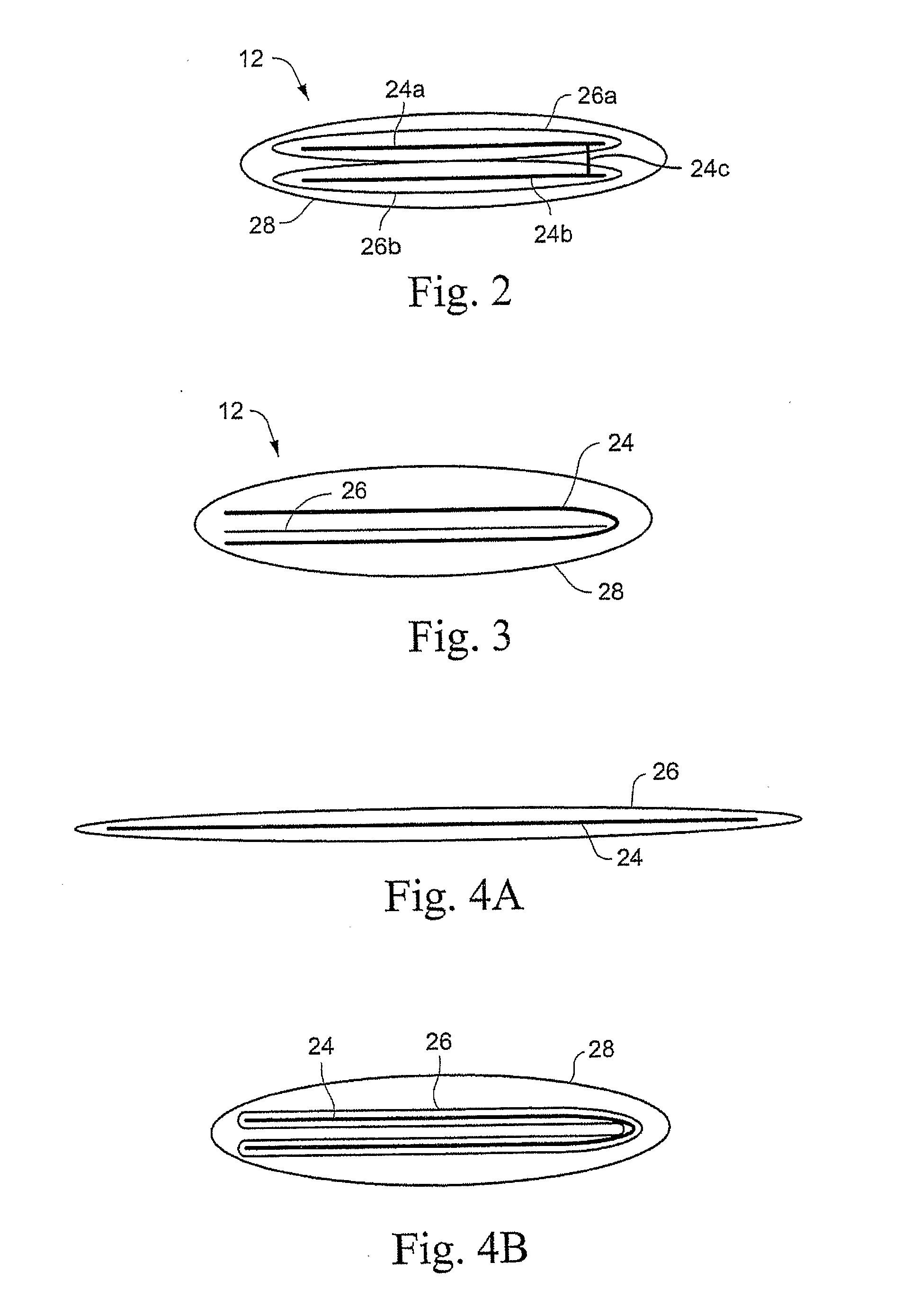
[0046]As shown in FIG. 2, the heating element 12 may comprise two resistive ribbon wires 24a, 24b. An insulating layer 26a, 26b is provided around each resistive ribbon wire 24a, 24b to provide dielectric insulation between at least two sections of the resistive ribbon wires 24a, 24b. The insulating layers 26a, 26b may be optionally encapsulated in a protective outer layer 28 to provide waterproofing and electrical safety requirements. The resistive ribbon wires 24a, 24b are electrically connected by a connection 24c, for example a spot weld, to provide an electrical connection to complete the circuit. The two ends 24d, 24e (FIG. 6) of the resistive ribbon wires 24a, 24b are exposed by removing portions of the insulating layers 26a, 26b (FIG. 7). The two ends 24d, 24e of the resistive ribbon wires 24a, 24b are connected to the power supply and controller 21 to provide a complete electrical circuit.

second embodiment

[0047]Heating Element Second Embodiment

[0048]Referring to FIG. 3, in another sample embodiment, the heating element 12 is formed of a single length of resistive ribbon wire 24 that is bent in half. An insulating layer 26 is placed between the two halves of the bent resistive ribbon wire 24. The outer protective layer or coating 28 is then formed around the bent resistive ribbon wire 24, for example by shrink wrapping or dipping.

third embodiment

[0049]Heating Element Third Embodiment

[0050]Referring to FIGS. 4A and 4B, in another sample embodiment of the heating element, a single resistive ribbon wire 24 is coated with an insulating layer 26 and the resulting structure is folded in half and then coated again in a second insulating layer or protective outer layer 28 to form the heating element 12.

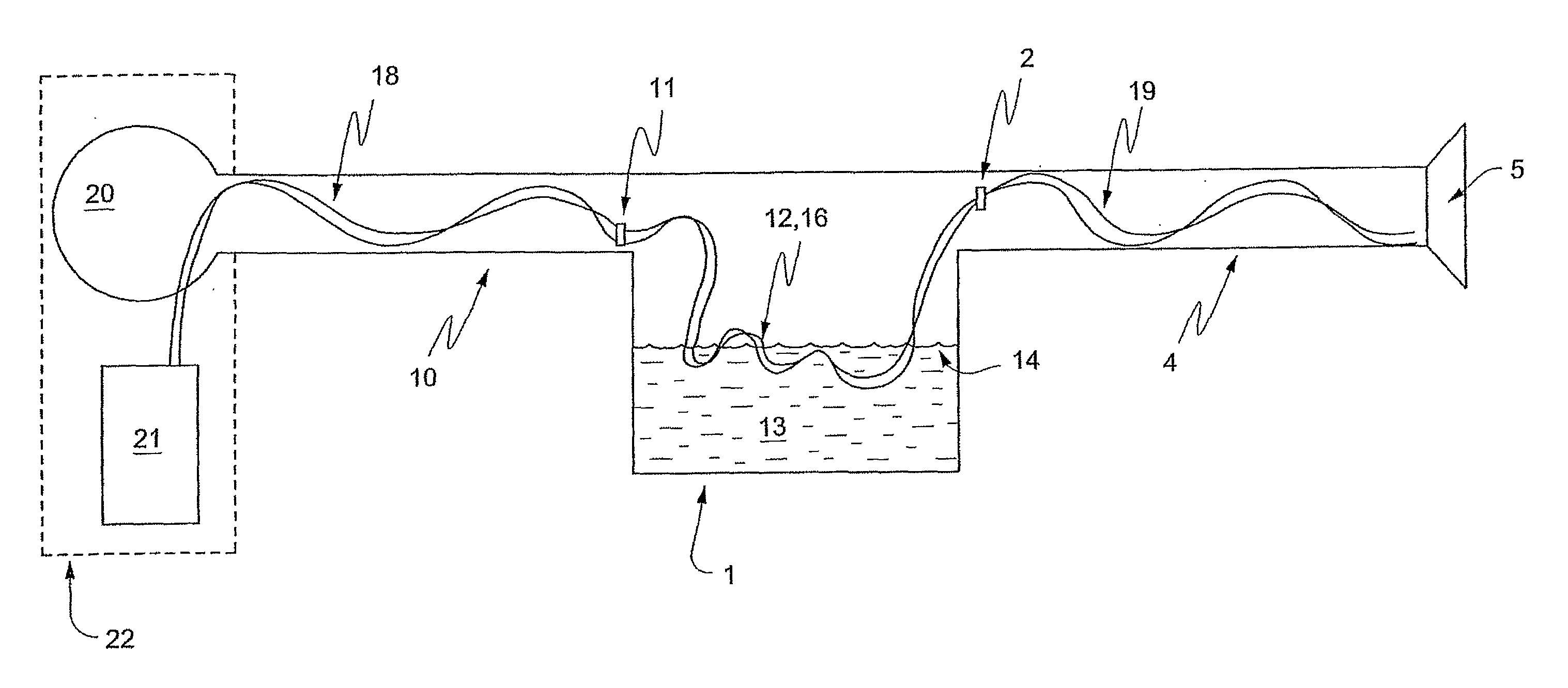
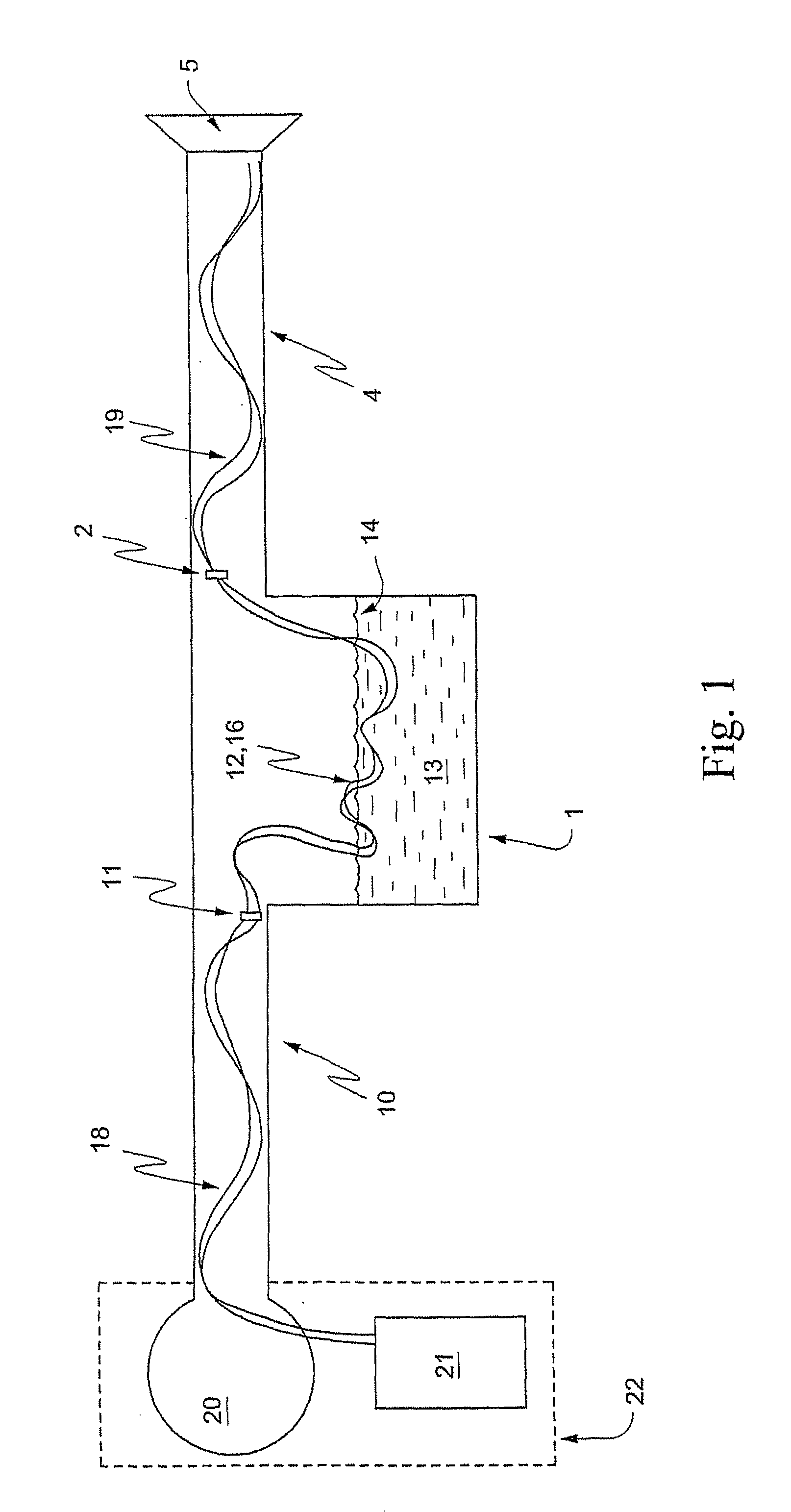
[0051]Heating Element and Delivery Conduit

[0052]As shown in FIG. 1 the heating element 12 may be incorporated within the inlet conduit 10 and / or the patient conduit 4. The heating element 12 may comprise different heating elements or zones. For example, as shown in FIG. 1, the heater element 12 may comprise a first heater element or zone 18 located in the inlet conduit 10, a second heater element or zone 16 located within the humidifier chamber 1, and a third heater element or zone 19 located in the patient conduit 4. Connectors 2, 11 provide the power and communication signals to each of the different heating elements or zones. Each...


PUM


Abstract

An apparatus for delivering breathable gas to a patient includes a flow generator to generate a flow of breathable gas; a humidifier chamber to contain a supply of water; a first flow path to deliver the flow of breathable gas from the flow generator to the humidifier chamber; a second flow path to deliver the flow of breathable gas from the humidifier chamber to a patient interface; and a wicking element and/or a flat, elongate heating element provided at least in the humidifier chamber. A method of delivering a flow of breathable gas to a patient includes generating a flow of breathable gas; and humidifying the flow by passing the flow over a supply of water. Humidifying the flow includes heating the supply of water and/or the flow with a heating element in thermal contact with the water and/or the flow before passing the supply of water, the flow over the supply of water, and/or the flow after passing the supply of water; and controlling a voltage applied to the heating element to control the humidity of the flow. A tube for use in delivering a flow of breathable gas to a patient includes a circuit including electrically conductive ink provided on an inner surface and/or an outer surface.

Description

CROSS REFERENCE TO RELATED APPLICATIONS[0001]This application claims priority to U.S. Application Nos. 60 / 952,899, filed Jul. 31, 2007, 61 / 021,372, filed Jan. 16, 2008, and 61 / 059,410, filed Jun. 6, 2008, the entire contents of each application being incorporated herein by reference.FIELD OF THE INVENTION[0002]The present invention relates to humidification and heater arrangements used to control the humidity of breathable gases used in all forms of respiratory apparatus ventilation systems including invasive and non-invasive ventilation, Continuous Positive Airway Pressure (CPAP), Bi-level therapy and treatment for sleep disordered breathing (SDB) conditions such as Obstructive Sleep Apnea (OSA), and for various other respiratory disorders and diseases.BACKGROUND OF THE INVENTION[0003]Respiratory apparatus commonly have means to alter the humidity of the breathable gas in order to reduce drying of the patient's airway and consequent patient discomfort and associated complications. ...

Claims


Application Information

Patent Timeline
IPC IPC(8): A61M16/16
CPCA61M16/0066A61M16/1075A61M16/16A61M2205/3368A61M2205/3653A61M16/1095A61M16/06A61M16/0875A61M16/108A61M16/1085A61M16/109A61M2205/8206
Inventor KLASEK, PAUL JANHEIDMANN, DIETER
Owner RESMED LTD
Why Eureka
Try Eureka