
Electronic fabric and preparing thereof

Inactive Publication Date: 2010-08-19
KOLON GLOTECH INC
View PDF4 Cites 137 Cited by
  • Summary
  • Abstract
  • Description
  • Claims
  • Application Information

AI Technical Summary

Benefits of technology

[0053]According to the electronic fabric and the preparing thereof, an electronic fabric in which a pattern can be freely formed without any restriction to ensure dynamic wearability as well as to generate an electronic signal and embedding recognition function is provided. Further, according to the electronic fabric and the preparing thereof, a circuit can be designed regardless of bending or folding due to the elasticity, flex resistance, and flexibility of a fiber as a material for a base layer to substantially prevent the circuit from damage, such as disconnection.
[0054]Further, the electronic fabric and the preparing thereof perform a function to generate an electronic signal while retaining inherent functions (e.g., coatability, comfort, breathable waterproofness and tensile strength) of fabric (i.e. clothing).
[0055]Further, a

Problems solved by technology

In view of above, it is difficult to design the proposed electrically conductive textiles for smart clothes so as to correspond to the placement and form of electronic devices.
In other words, no alternative can be provided in view of the physical requirements for wearers and devices.
Furthermore, the proposed fabrics suffer from great limitations in fiber volume

Method used


Image

  • Electronic fabric and preparing thereof
  • Electronic fabric and preparing thereof
  • Electronic fabric and preparing thereof

Examples


Example

BRIEF EXPLANATION OF ESSENTIAL PARTS OF THE DRAWINGS

[0073]

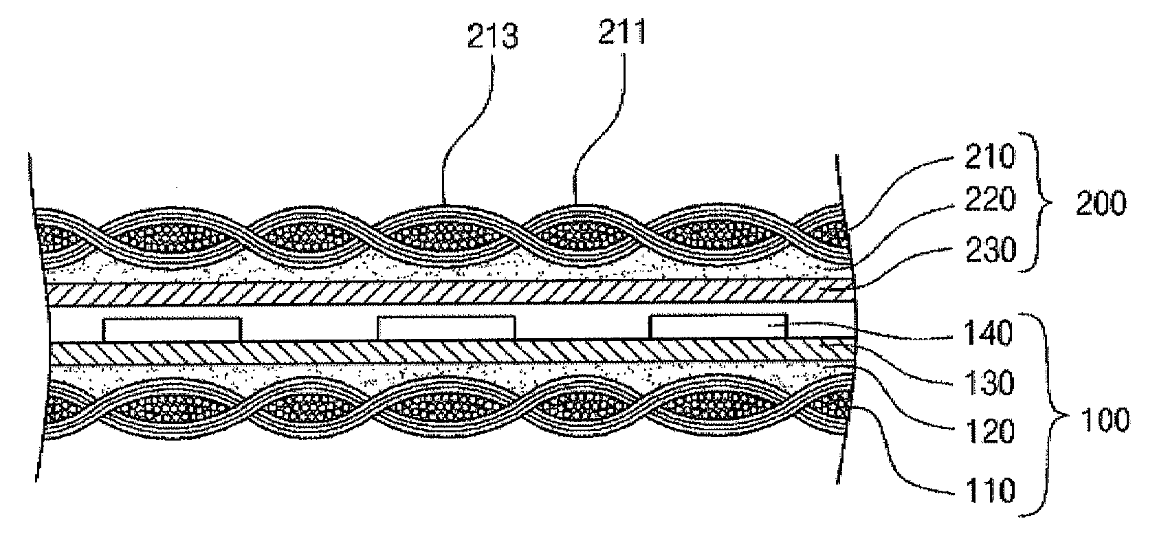
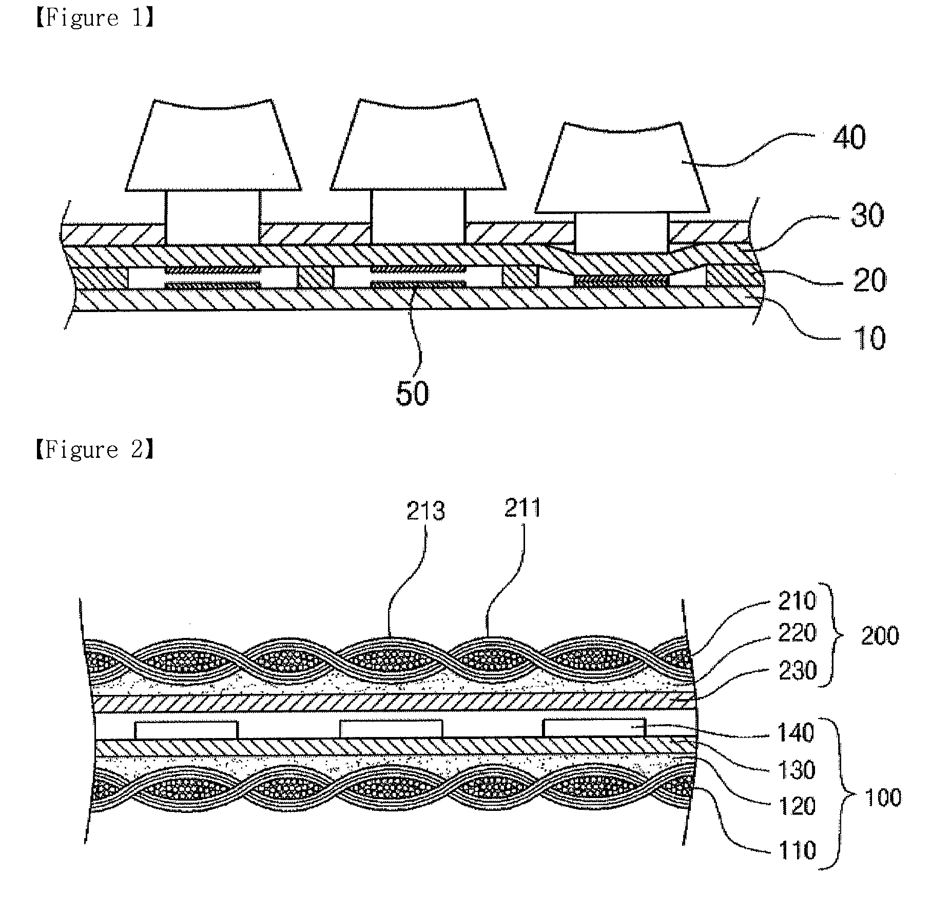
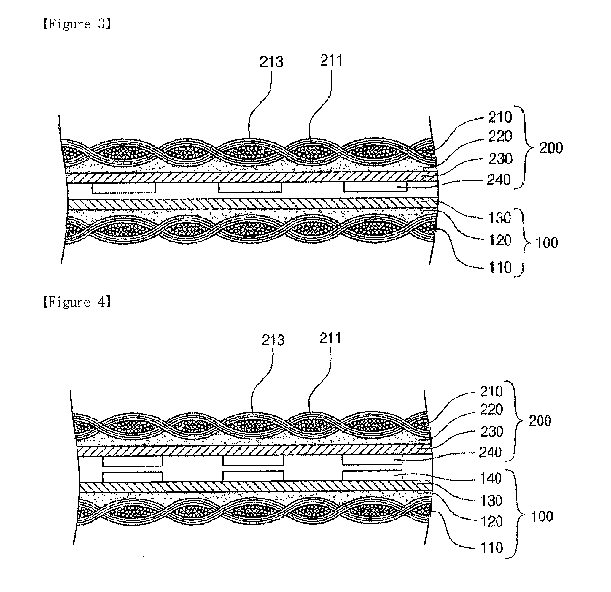
100: Backing layer,200: Surface layer,110, 210: Base layer,120, 220: Primer layer130, 230: Conductive layer,140, 240: Insulating layer250, 310: Printing layer,400: Filling Member211, 311: Protrusion portion,213, 313: Concave portion

Best Mode

[0074]Preferred embodiments of the present invention will now be described in detail with reference to the accompanying drawings. It should be noted that whenever possible, the same reference numerals will be used throughout the drawings and the description to refer to the same or like parts. In describing the present invention, detailed descriptions of related known functions or configurations are omitted in order to avoid making the essential subject of the invention unclear.

[0075]As used herein, the terms “about”, “substantially” etc. are intended to allow some leeway in mathematical exactness to account for tolerances that are acceptable in the trade and to prevent any unconscientious ...


PUM

PropertyMeasurementUnit
Thicknessaaaaaaaaaa
Thicknessaaaaaaaaaa
Surfaceaaaaaaaaaa

Abstract

Disclosed herein is an electronic fabric and preparing thereof. The electronic fabric comprises a backing layer configured to have a circuit electrically floated and a surface layer configured to electrically connect to the circuit of the backing layer. The backing layer or the surface layer comprises a) a base layer composed of a synthetic, regenerated or natural fiber and b) a conductive layer formed on the base layer to be capable of being freely formed by a pre-designed electric pattern. The base layer and the conductive layer are successively formed to be symmetrically to the backing layer and the surface layer to each other. An insulating layer is formed on the backing layer or the surface layer, or a partial upper portion of the conductive layer, or in a region where the conductive layer is not formed.

Description

TECHNICAL FIELD[0001]The present invention relates to an electronic fabric and preparing thereof, and more particularly to an electronic fabric capable of generating an electronic signal, transmitting the electronic signal, and processing and displaying the transmitted electronic signal without any restriction to dynamic wearability.BACKGROUND ART[0002]Smart clothes result from bonding high technology and clothe are derived from body-mounted wearable computers by separating computer apparatus in 1960s. Wearable computers are defined as computers that are subsumed or integrated into the personal space of a user and controlled by the user and are a constant interaction between the computers and user. For example, wearable computers can be operated in any time because power supply is always turned on and considered as computers combined with clothes. Recently, the concept of smart clothes has been changed and defined as brand new cloth having life convenience as well as providing high ...

Claims


Application Information

Patent Timeline
IPC IPC(8): H01B5/00B05D5/12B32B3/00
CPCH01H13/88H01H2203/0085H01H2223/008H01H2229/002Y10T428/24355H05K3/281H05K2201/029H01H13/704H05K1/038H01H9/00H05K9/00
Inventor PARK, SUNG MEECHO, KWANG SUCHUNG, KYUNG HEE
Owner KOLON GLOTECH INC
Learn More