Parking brake system

a brake system and parking technology, applied in the direction of brake systems, drum brakes, actuators, etc., can solve the problems of making other brake shoes difficult to be separated from the anchorage, and achieve the effect of reducing the brake force, facilitating movement, and facilitating movemen

Active Publication Date: 2010-08-19
TOYOTA JIDOSHA KK
View PDF9 Cites 25 Cited by
  • Summary
  • Abstract
  • Description
  • Claims
  • Application Information

AI Technical Summary

Benefits of technology

[0024]In each of the parking brake system disclosed by JP-2001-82517A and JP-2006-33686A, there is provided a pressing device in which a pressing force is applied by an electric actuator to both of the pair of brake shoes in each of these parking brake systems, it is not determined which one of the brake shoes is to be moved. Therefore, upon application of a torque to the wheel during a brake effect state, the pair of brake shoes could be rotated in a direction in which the torque acts on the wheel so that the secondary shoe could be brought into contact with one of the sliding members so as to apply a large force to the one of the sliding members. On the other hand, in the parking brake system according to this mode (2), since the secondary shoe is in contact with the anchor member, the force acting in a circumferential direction is received by the anchor member rather than by the at least one acting member. Consequently, the at least one acting member does not have to have a large strength, so that the pressing device as a whole can be made compact in size and the manufacturing cost can be reduced. Further, since it is possible to reduce frequency of application of a large force to the at least one acting member, service life of the at least one acting member can be increased.
[0126]In the parking brake system according to mode (23), the movable member of the pressing mechanism is moved to apply a pressing force only to a predetermined one of the pair of brake shoes, whereby the parking brake is brought into effect. The movable member, which may be a rod-like member, for example, does not have flexibility and is arranged to be linearly movable, unlike a flexible cable and a pivotable lever. Upon application of a torque to the wheel while the parking brake is being in effect during stop of the vehicle, the secondary shoe is brought into contact with the anchor member while the primary shoe is brought into contact with the movable member. Therefore, a reduction of the braking force is satisfactorily restrained, irrespective of whether the pressing force is applied to the primary or secondary shoe as the predetermined one of the brake shoes. In an arrangement in which the predetermined one of the brake shoes is the primary shoe upon application of the torque to the wheel in the forward rotation direction, there is an advantage that a large braking force can be obtained when the brake is activated during a forward running of the vehicle. In this arrangement, since a large force is not applied to the movable member, the movable member does not have to have a large strength and a large braking force can be obtained.

Problems solved by technology

Owing to this arrangement, the other of the brake shoes can be made difficult to be separated from the anchor when the brake shoes are pressed against the drum.

Method used


Image

  • Parking brake system
  • Parking brake system
  • Parking brake system

Examples


Embodiment Construction

[0164]There will be described embodiments of the present invention, by reference to the accompanying drawings. It is to be understood that the present invention is not limited to the following embodiments, and may be otherwise embodied with various changes and modifications, such as those described in the foregoing “MODES OF THE INVENTION”, which may occur to those skilled in the art.

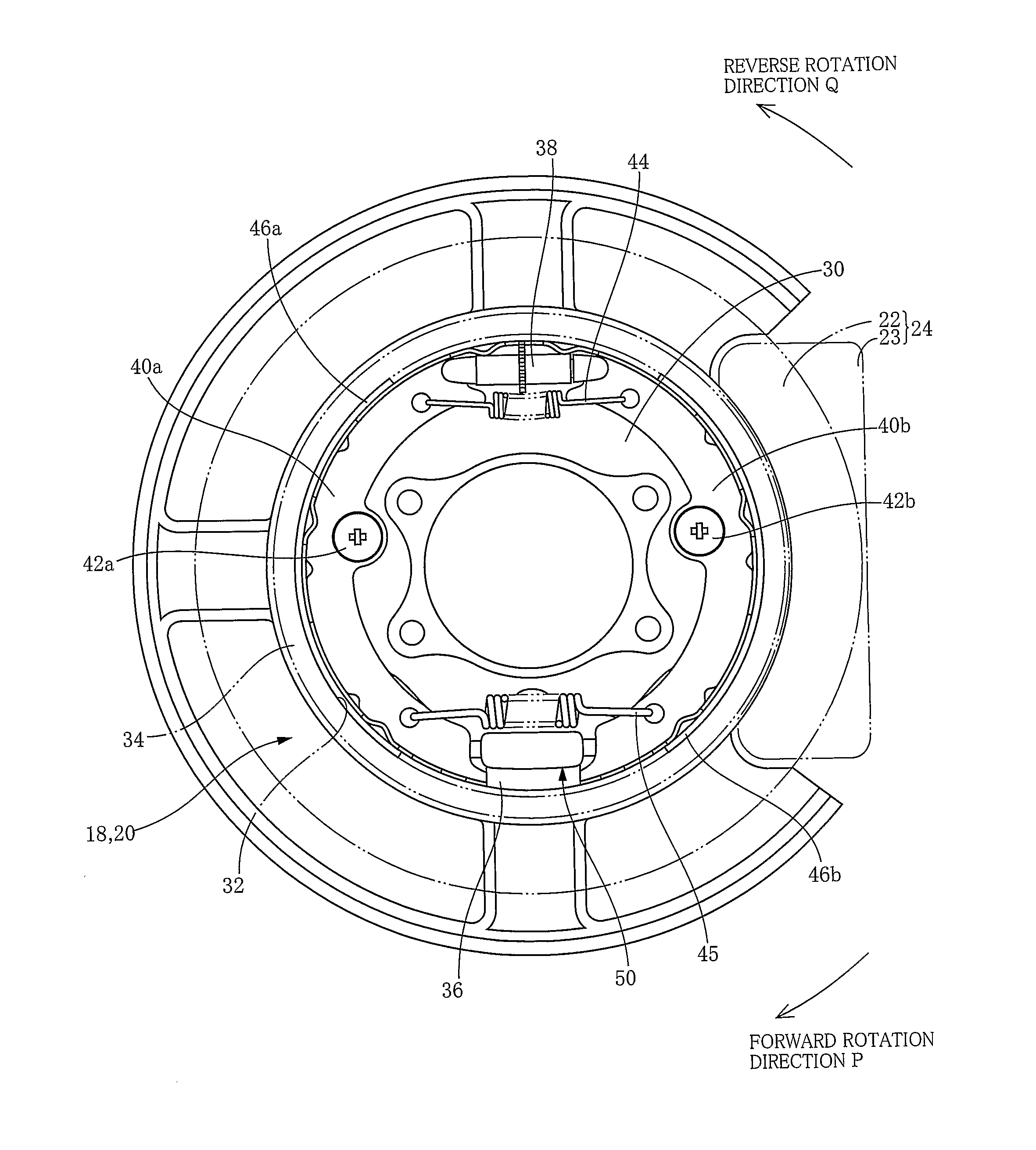
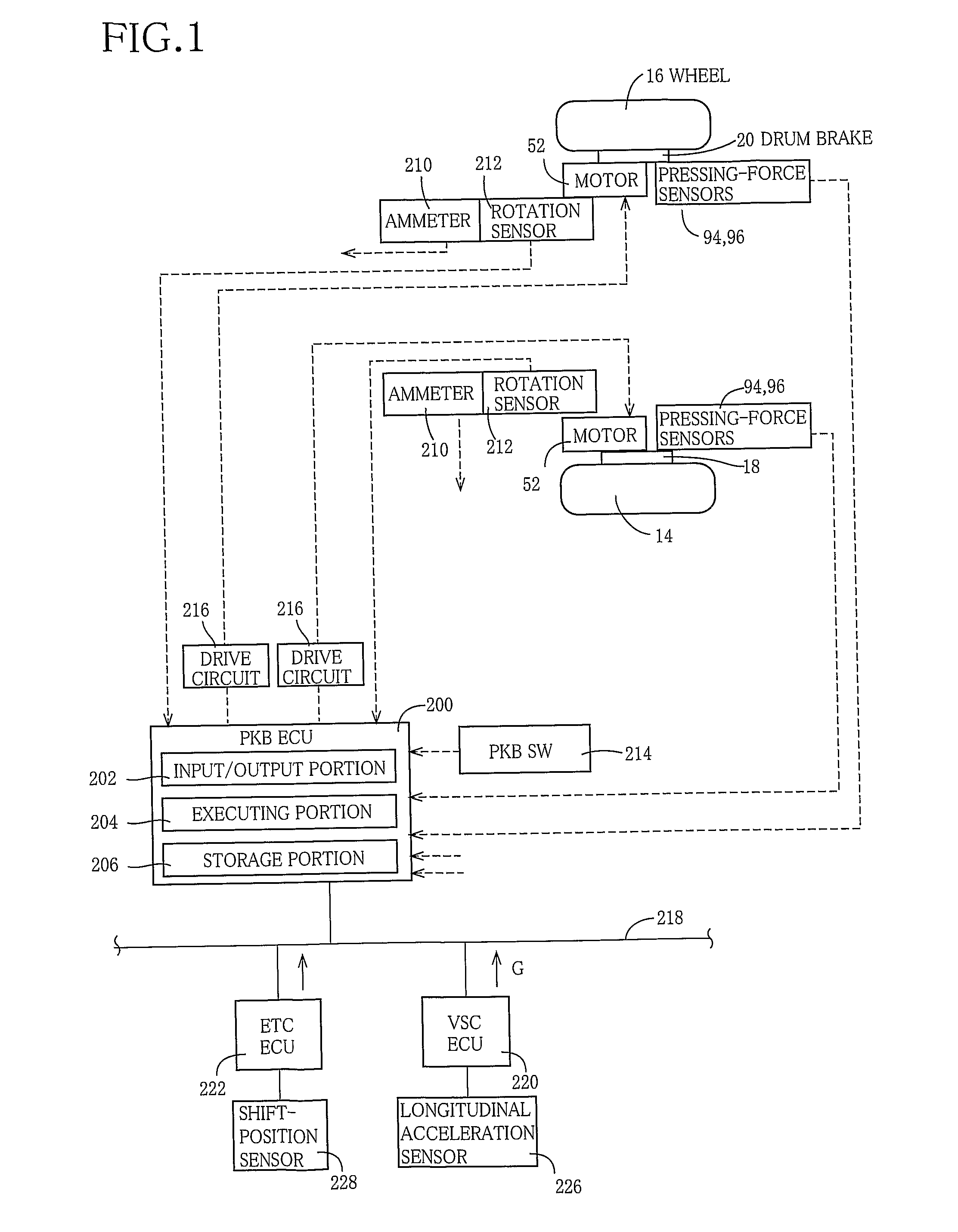
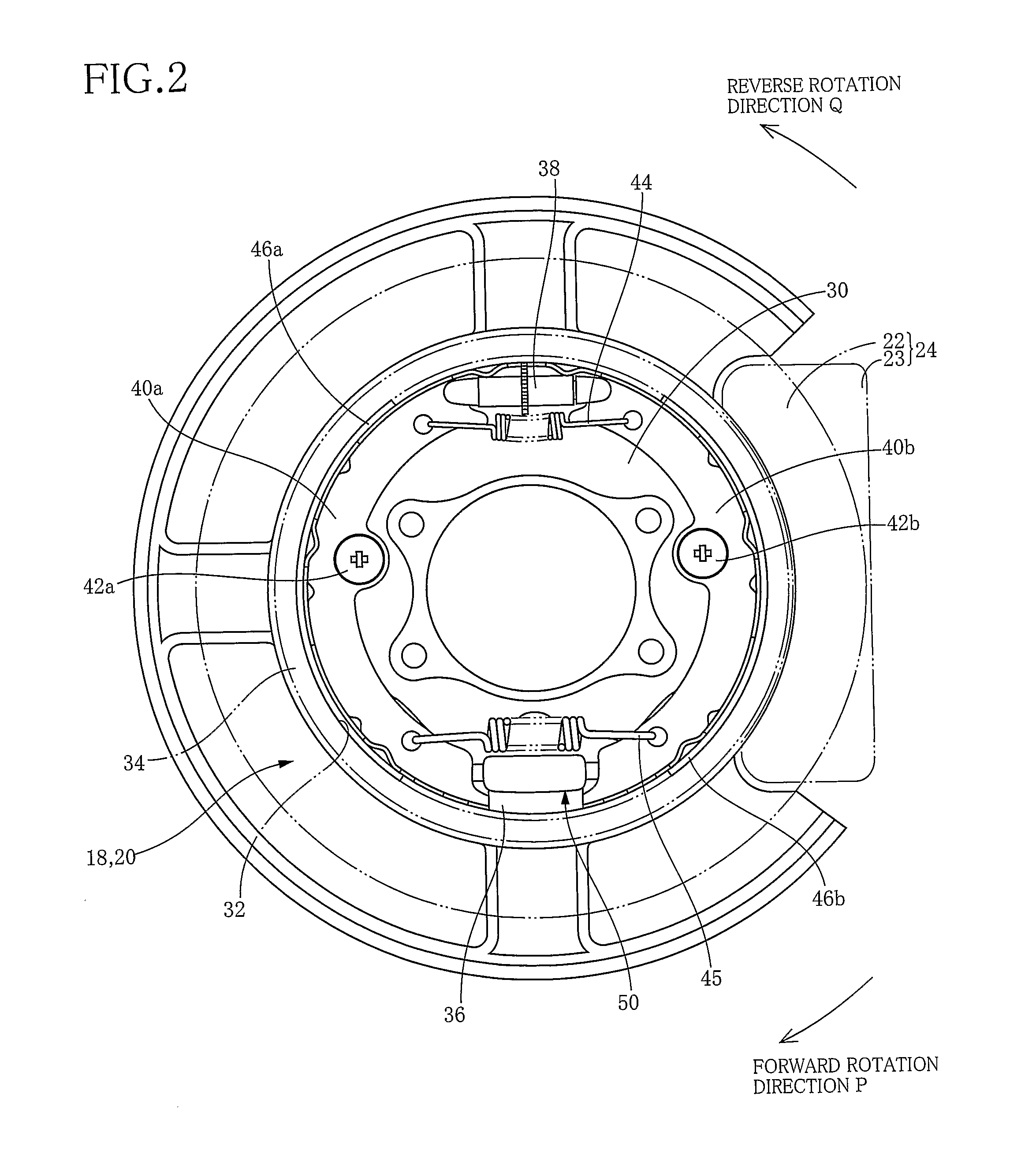
[0165]Referring first to FIGS. 1-18, there will be described a parking brake system constructed according an embodiment of the invention. In FIG. 1, reference signs 16, 14 denote rear right and rear left wheels of a vehicle, respectively, and reference signs 18, 20 denote drum brakes that are provided for the respective wheels 14, 16. As shown in FIG. 2, each of the drum brakes 18, 20 is a duo-servo drum brake that is incorporated in the parking brake system. Since each of the drum brakes 18, 20 functions as a parking brake, it will be hereinafter referred to as a parking brake where appropriate. In FIG...


PUM


Abstract

A vehicle parking brake system for a vehicle including: a non-rotary body; a rotary drum; brake shoes; an anchor member disposed between anchor-member-side end portions of the respective brake shoes; a transmitting member interconnecting transmitting-member-side end portions of the respective brake shoes; and a parking-brake operating apparatus configured to predict a torque application direction in which a torque is to be applied to the wheel during stop of the vehicle, and to press the brake shoes against an inner circumferential surface of the rotary drum, by moving a primary one of the brake shoes that serves as a primary shoe upon application of the torque to the wheel, in a direction away from the anchor member, without moving a secondary one of the brake shoes that serves as a secondary shoe upon application of the torque to the wheel.

Description

TECHNICAL FIELD[0001]The present invention relates in general to a parking brake system including a drum brake.BACKGROUND ART[0002]JP-H10-110758A, JP-2001-165207A and JP-H10-103391A disclose duo-servo parking brakes in each of which, when a cable is pulled, a pair of brake shoes are moved through a brake lever and a strut so as to be pressed against a rotary drum whereby the parking brake is brought into effect. JP-2001-82517A discloses an electrically-operated parking brake system having a duo-servo drum brake. This parking brake system includes a pressing device having (a) an electric motor, (b) a pair of sliding members, (c) a motion converting mechanism disposed between the electric motor and the sliding members, and configured to convert a rotary motion which is to be given from the electric motor, into linear motions which are directed in respective opposite directions and which are to be given to the respective sliding members, and (d) a motor controlling portion configured t...

Claims


Application Information

Patent Timeline
Patent Type & Authority Applications(United States)
IPC IPC(8): F16D51/20
CPCB60T13/741B60T13/746F16D2121/24F16D2125/30F16D2127/06F16D2125/34F16D2125/40F16D2125/42F16D2125/52F16D2125/32
Inventor SHIRAKI, TAKAHIRO
Owner TOYOTA JIDOSHA KK
Why Eureka
Try Eureka