
Portable hand wash monitoring system and method

a monitoring system and portable technology, applied in the field of security systems, can solve the problems of inability to install a permanent monitoring system, inability to detect redundancy, and inability to monitor the hand wash,

Active Publication Date: 2010-08-19
VERDIRAMO VINCENT L
View PDF16 Cites 13 Cited by
  • Summary
  • Abstract
  • Description
  • Claims
  • Application Information

AI Technical Summary

Benefits of technology

[0017]In the preferred embodiment, the dispenser controller comprises an electric motor and a helical screw conveyor. The activation signal causes the electric motor to be activated for a designated time interval. The motor has a shaft which rotates when the motor is activated. The shaft is coupled to the helical screw conveyor by a gearing means, consisting to two gears, which can be spur, helical, worm, or bevel gears. Thus, when the motor is activated by the activation signal, the helical screw conveyor rotates for the designated time interval, thereby drawing a set quantity of hand wash solution out of the storage tank, which is fluidly connected to the dispenser controller. The set quantity of hand wash solution dispensed is determined by the system control device based on the rotational speed of the motor, the gear ratio, the designated time interval, and the depth and pitch of the thread of the helical screw conveyor.
[0...

Problems solved by technology

The preferred embodiment described in the 2008 Hand Wash Patent has the disadvantage of having redundant hand detection apparatus in the hand wash station, insofar as it requires both a pair of indicator readers and a sensor light emitter-receiver pair, with the former serving to detect the indicator device on the monitored individual's hands and the latter serving to dispense soap onto the individual's hands.
This redundancy adds both to the expense of the hand cleaning station and the potential for malfunction.
Such activities typically occur at locations where installation of a permanent monitoring system is not feasible, or where conventional indoors lavatories are not available.

Method used


Image

  • Portable hand wash monitoring system and method
  • Portable hand wash monitoring system and method
  • Portable hand wash monitoring system and method

Examples


Embodiment Construction

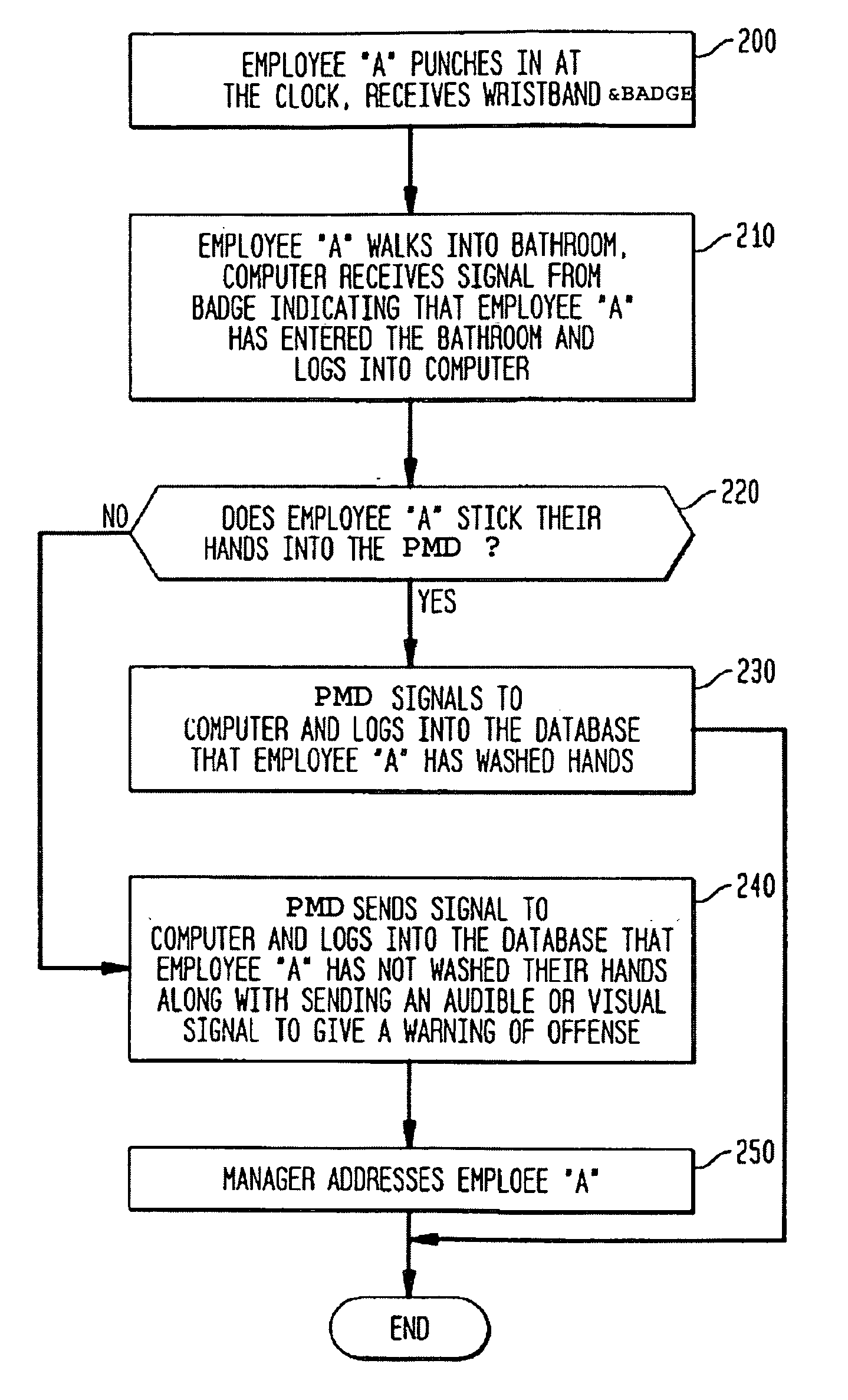
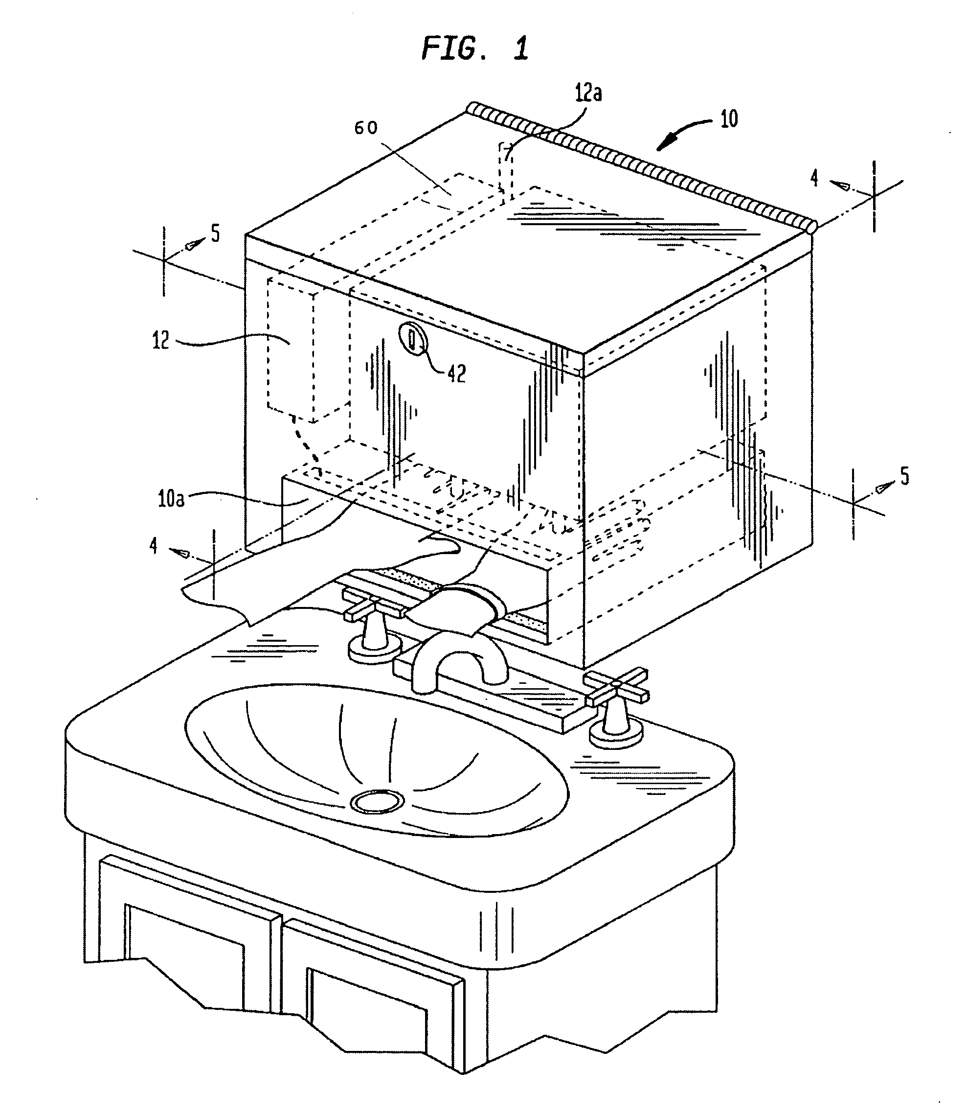
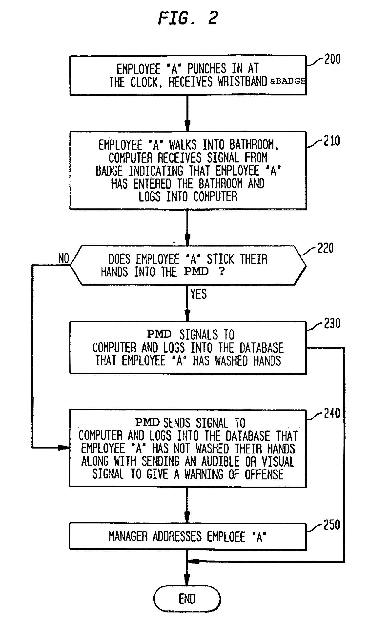
[0028]FIG. 1 is a perspective view illustrating a portable hand wash monitoring system embodying the present invention, in use by an individual. A portable monitoring dispenser (PMD) 10 is provided in the washroom in close proximity to a cleaning area, which in this illustrative case comprises a faucet and a sink. The PMD 10 has a dispenser opening 10a, into which an individual inserts his hands prior to washing them. As will be explained below, the insertion of the hands is sensed by the PMD 10, which dispenses soap. The station also provides an indication to the system that the hands have been inserted.

[0029]FIG. 3 is functional block diagram illustrating the major components of the hand wash system and their cooperation. The three major components are a remote data retrieval means, which in this illustrative example is a remote computer 20; an identity sensor 30 provided near a door or access to a lavatory area, where an individual would enter and leave the lavatory area; and the...


PUM


Abstract

An identification badge worn by an individual is sensed when that individual enters a lavatory area. The individual is also provided with an indicator device which is worn on or about the hands. Inside or in proximity to the lavatory, there is also provided a hand cleaning area, within which is a portable monitoring dispenser, which includes a pair of indicator readers that detect the presence of the indicator device and cause soap to be dispensed on the individual's hands, then provides an appropriate indication to a computer system. Should the badge sensor sense the individual's departure from the lavatory area without an appropriate indication being generated by the indicator readers, a warning signal is generated, which is sent to the computer system and to an appropriate officer, who can then address the individual.

Description

CROSS-REFERENCE TO RELATED APPLICATIONS[0001]The present application is a continuation-in-part of U.S. application Ser. No. 12 / 379,130, filed Feb. 13, 2009.FIELD OF THE INVENTION[0002]The present invention relates generally to security systems and, more particularly, concerns a portable system and method for monitoring whether individuals using a lavatory or similar facility wash their hands.BACKGROUND OF THE INVENTION[0003]The present invention is an improvement of the “Hand Wash Monitoring System and Method” as disclosed in U.S. Pat. No. 7,443,305, issued Oct. 28, 2008, to Vincent L. Verdiramo, which patent is hereafter referred to as the “2008 Hand Wash Patent”, the contents of which are incorporated herein by reference. The present invention is an alternate embodiment of the “Improved Hand Wash Monitoring System and Method” disclosed in U.S. patent application Ser. No. 12 / 379,130, filed Feb. 13, 2009, by Vincent L. Verdiramo (of which this application is a continuation-in-part),...

Claims


Application Information

Patent Timeline
IPC IPC(8): G08B23/00
CPCG08B21/245
Inventor VERDIRAMO, VINCENT L.
Owner VERDIRAMO VINCENT L
Learn More