Devices and methods for reducing artefacts in display devices by the use of overdrive

a display device and artefact technology, applied in static indicating devices, cathode-ray tube indicators, instruments, etc., can solve the problems of reducing clinical accuracy by up to 10%, slow response time of pixels of liquid crystal displays, and inability to reduce the magnitude of clinical accuracy, so as to reduce imaging artefacts, reduce imaging artefacts, and reduce the effect of display images

Active Publication Date: 2010-08-19
BARCO NV
View PDF14 Cites 133 Cited by
  • Summary
  • Abstract
  • Description
  • Claims
  • Application Information

AI Technical Summary

Benefits of technology

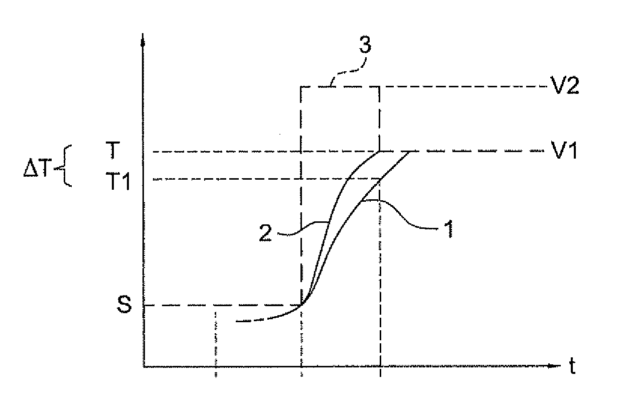
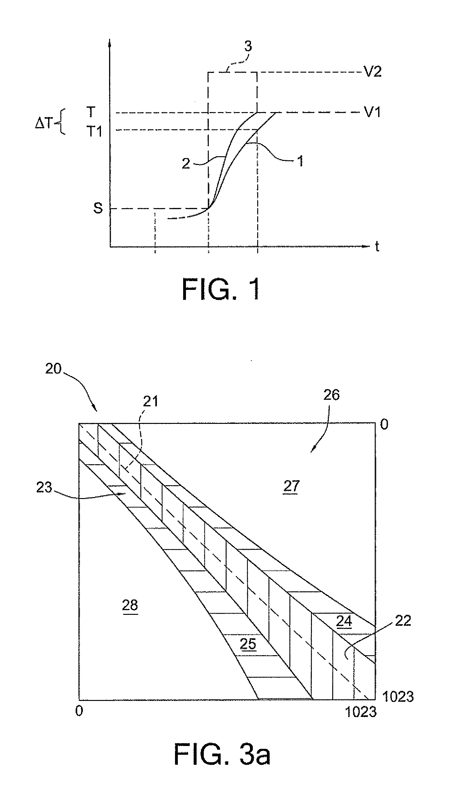
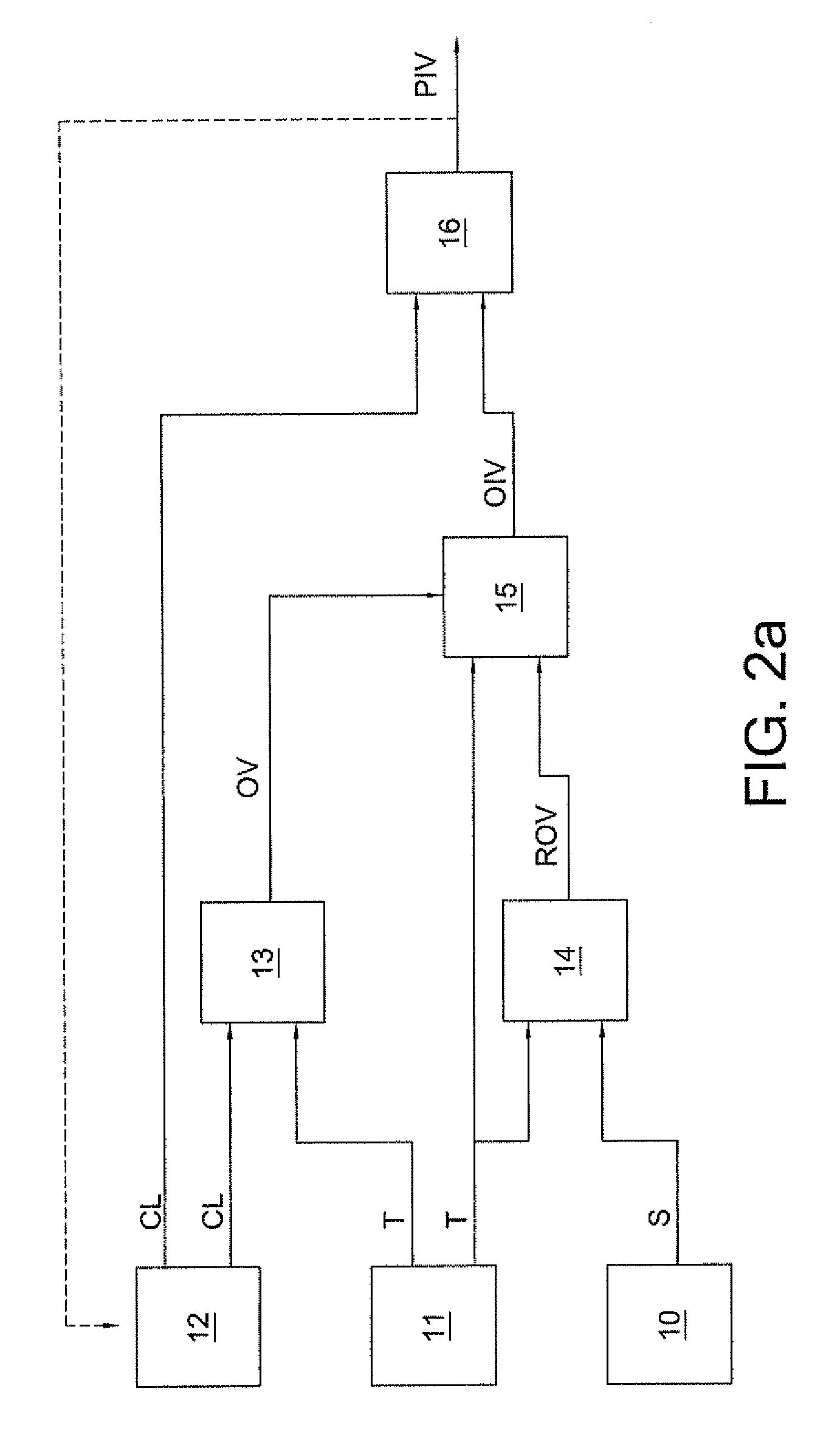
[0011]An advantage of the present invention is the provision of a device, controllers for controlling the operation of display devices, software and method for reducing imaging artefacts during a frame-changeover from a current frame to a following frame. A device, controllers for controlling the operation of display devices, software and method for reducing imaging artefacts in accordance with embodiments of the present invention take into account typical noise characteristics of the pictured images so as to reduce artefacts in the displayed images.
[0012]To achieve this object, the present invention provides a device, of a device, a controller for controlling the operation of display devices, software and a method for reducing imaging artefacts during a frame-changeover from a current frame to a following frame displayed by a liquid crystal display device comprising a plurality of pixels by overdriving at least one control signal during the frame-changeover.
[0013]In embodiments of the invention the artefacts are reduced by overdriving at least one control signal...

Problems solved by technology

The liquid crystal display suffers from slow response time of the pixels.
Studies have shown that reading at a speed of ten slices per second on a typical medical display like a standard 5 megapixel (5 MP) mammography display device can result in a decrease of clinical accuracy of up to 10%.
The magnitude of this decrease is not acceptable.
The slow response time of LCD pixels is a well known problem.
Typically, medical images are rather noisy which means that the change within two consecutive images can be simply caused by image noise e.g. caused by the detector system.
Standard liquid crystal display devices, as a side effect of their slow response time, unintentionally apply noise red...

Method used


Image

  • Devices and methods for reducing artefacts in display devices by the use of overdrive
  • Devices and methods for reducing artefacts in display devices by the use of overdrive
  • Devices and methods for reducing artefacts in display devices by the use of overdrive

Examples


Embodiment Construction

[0035]The present invention will be described with respect to particular embodiments and with reference to certain drawings but the invention is not limited thereto but only by the claims. The drawings described are only schematic and are non-limiting. In the drawings, the size of some of the elements may be exaggerated and not drawn on scale for illustrative purposes.

[0036]Furthermore, the terms first, second, third and the like in the description and in the claims, are used for distinguishing between similar elements and not necessarily for describing a sequential or chronological order. It is to be understood that the terms so used are interchangeable under appropriate circumstances and that the embodiments of the invention described herein are capable of operation in other sequences than described or illustrated herein.

[0037]Moreover, the terms top, bottom, over, under and the like in the description and the claims are used for descriptive purposes and not necessarily for descri...


PUM


Abstract

The invention relates to a method for reducing imaging artefacts during a frame-changeover from a current frame to a following frame displayed by a display device comprising a plurality of pixels, wherein the artefacts are reduced by overdriving at least one control signal for controlling the pixel intensity of the related pixel during the frame-changeover, wherein the overdrive is carried out in dependence of the magnitude of an intensity step between a designated start intensity value of the pixel within the current frame and a designated target intensity value of the pixel within the following frame.

Description

[0001]The invention relates to display devices, controllers for controlling the operation of display devices, software and methods of driving display devices. In particular, the present invention relates to a display device, a controller for controlling the operation of a display device, software and a method for reducing imaging artefacts during a frame-changeover from a current frame to a following frame displayed by a display device comprising a plurality of pixels by overdriving at least one control signal during the frame-changeover.TECHNICAL BACKGROUND[0002]In modern medical facilities, high-quality medical imaging using display devices like liquid crystal display devices (LCD devices) is more important than ever before. Each pixel of a liquid crystal display panel (LCD panel) of the LCD device is assumed to a discrete intensity value (luminance value) of a set of values, e.g. a set of values with a bit depth of 10 bits [0 . . . 1023], wherein a pixel group of three of these p...

Claims


Application Information

Patent Timeline
IPC IPC(8): G09G5/00
CPCG09G3/2044G09G3/3648G09G2320/0247G09G2360/18G09G2320/041G09G2320/0666G09G2340/16G09G2320/0252
Inventor KIMPE, TOMMARCHESSOUX, CEDRIC
Owner BARCO NV
Why Eureka
Try Eureka