Backlight device and liquid crystal display

a backlight device and liquid crystal display technology, applied in the direction of illuminated signs, display means, instruments, etc., can solve the problems of deteriorating image quality affecting the uniformity of luminance on the screen of liquid crystal display including the means, and affecting the uniformity of luminance on the screen of liquid crystal display, so as to prevent luminance on the diffuser plate, maintain the constant distance between the diffuser plate and the light source, and achieve uniformity. uniform

Inactive Publication Date: 2010-08-19
JVC KENWOOD CORP A CORP OF JAPAN
View PDF25 Cites 35 Cited by
  • Summary
  • Abstract
  • Description
  • Claims
  • Application Information

AI Technical Summary

Benefits of technology

[0024]The present invention is invented in order to solve the above-described problems, and has an object to provide a backlight device that prevents luminance on a diffuser plate from lacking in uniformity while keeping a distance between the diffuser plate and a light source constant, and a liquid crystal display provided with the backlight device.
[0025]The present invention has another object to provide a backlight device that prevents luminance on a part of a diffuser plate corresponding to an engagement portion where a supporting member is engaged to a diffuser plate and / or a reinforcing member is engaged to the diffuser plate and an adjacent portion around the engagement portion, from lacking in uniformity, and a liquid crystal display provided with the backlight device.
[0036]According to the present invention, the backlight device and the liquid crystal display provided with the backlight device prevent luminance on the diffuser plate from lacking in uniformity while keeping a distance between the diffuser plate and the light source constant.

Problems solved by technology

This deteriorates image quality of the liquid crystal display.
However, if a light blocking pattern of the lighting curtain is not in a right position with respect to light sources, the means can not completely eliminate a lamp image using a diffuser sheet (diffuser plate) or an optical sheet such as a prism sheet.
This causes luminance on a screen of a liquid crystal display including the means to lack in uniformity.
This also causes luminance on the screen of the liquid crystal display to lack in uniformity.
However, a recent liquid crystal display is relatively large to meet a demand for enlarging a screen (liquid crystal panel) of liquid crystal display.
This causes the diffuser plate to bending by its own weight.
However, although preventing the lighting curtain (or diffuser plate) from bending toward a light source side of a liquid crystal display including the means, the spacer can not prevent the light curtain (or diffuser plate) from bending toward a liquid crystal panel side of the liquid crystal display.
In addition, if the light curtain (or diffuser plate) bends toward the liquid crystal panel side, there is a possibility that an optical sheet attached to the diffuser plate contacts with the liquid crystal panel to damage the liquid crystal panel.
If a surface area of each head of spacer is relatively large, this deteriorates visibility on a screen of a liquid crystal display.
This deteriorates visibility on the screen of the liquid crystal display.
However, once the fixing members are attached to the lighting curtain and / or the diffuser plate using an adhesive agent, a double-faced tape or the like, when a backlight device is taken apart in order to exchange a lamp or the like, there is a possibility that it is difficult to take apart the backlight device.
This deteriorates visibility on a screen of a liquid crystal display.
However, if the whole fixing member is made of transparent material, when light has passed through the fixing member to reach a surface of the backlight device without being diffused in the diffuser plate, this causes light leaking.
This causes luminance on the screen of the liquid crystal display to lack in uniformity.
Thus, it is difficult for the alternative way to keep uniformity of luminance on the screen of the liquid crystal display while preventing the diffuser plate from bending toward the liquid crystal panel side.
However, it is difficult to prevent the lighting curtain and / or the diffuser plate from bending toward the liquid crystal panel side using the ribs, with respect to a liquid crystal display including a large and thin liquid crystal panel more than or equal to 37 inches and a backlight device being about 10 mm thick.
Even if the ribs are thickened to increase rigidity of diffuser plate, the ribs interfere in light emitted from the light sources.
This causes luminance on the screen of the liquid crystal display to lack in uniformity, which deteriorates quality of the liquid crystal display.
In addition, in a conventional backlight device in which supporting members are employed to increase arrangement accuracy of the diffuse plate to prevent luminance on the diffuser plate from lacking in uniformity, there is a possibility of causing luminance on a part of the diffuser plate corresponding to engagement portions where the supporting members are engaged to the diffuser plate and adjacent portions around the engagement portions, to lack in uniformity.
This problem also occurs when reinforcing members are installed to increase rigidity of the diffuse plate for preventing the diffuser plate from bending toward the liquid crystal panel side.

Method used


Image

  • Backlight device and liquid crystal display
  • Backlight device and liquid crystal display
  • Backlight device and liquid crystal display

Examples


first exemplary embodiment

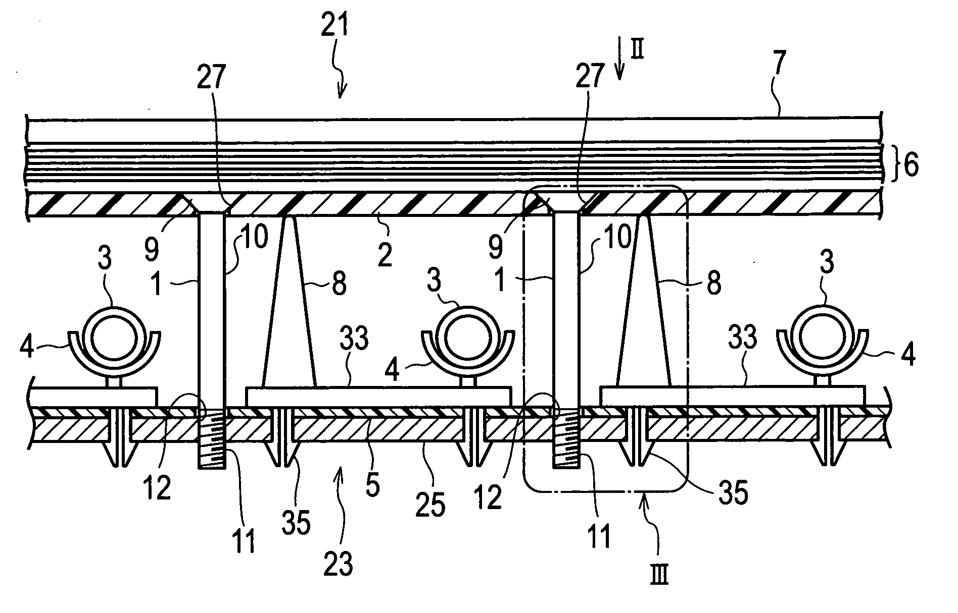
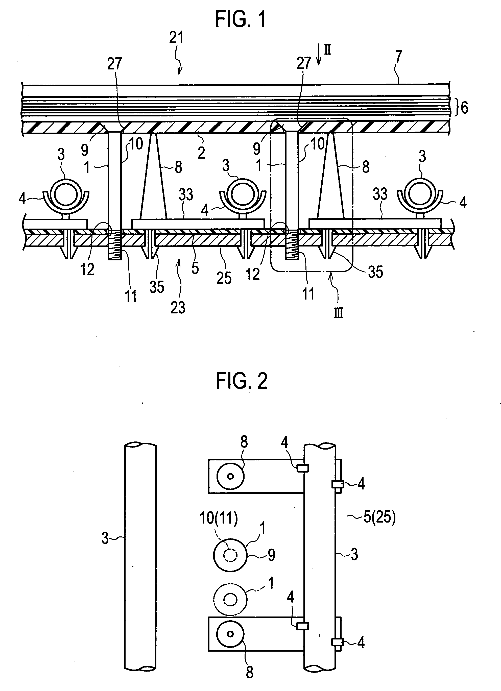
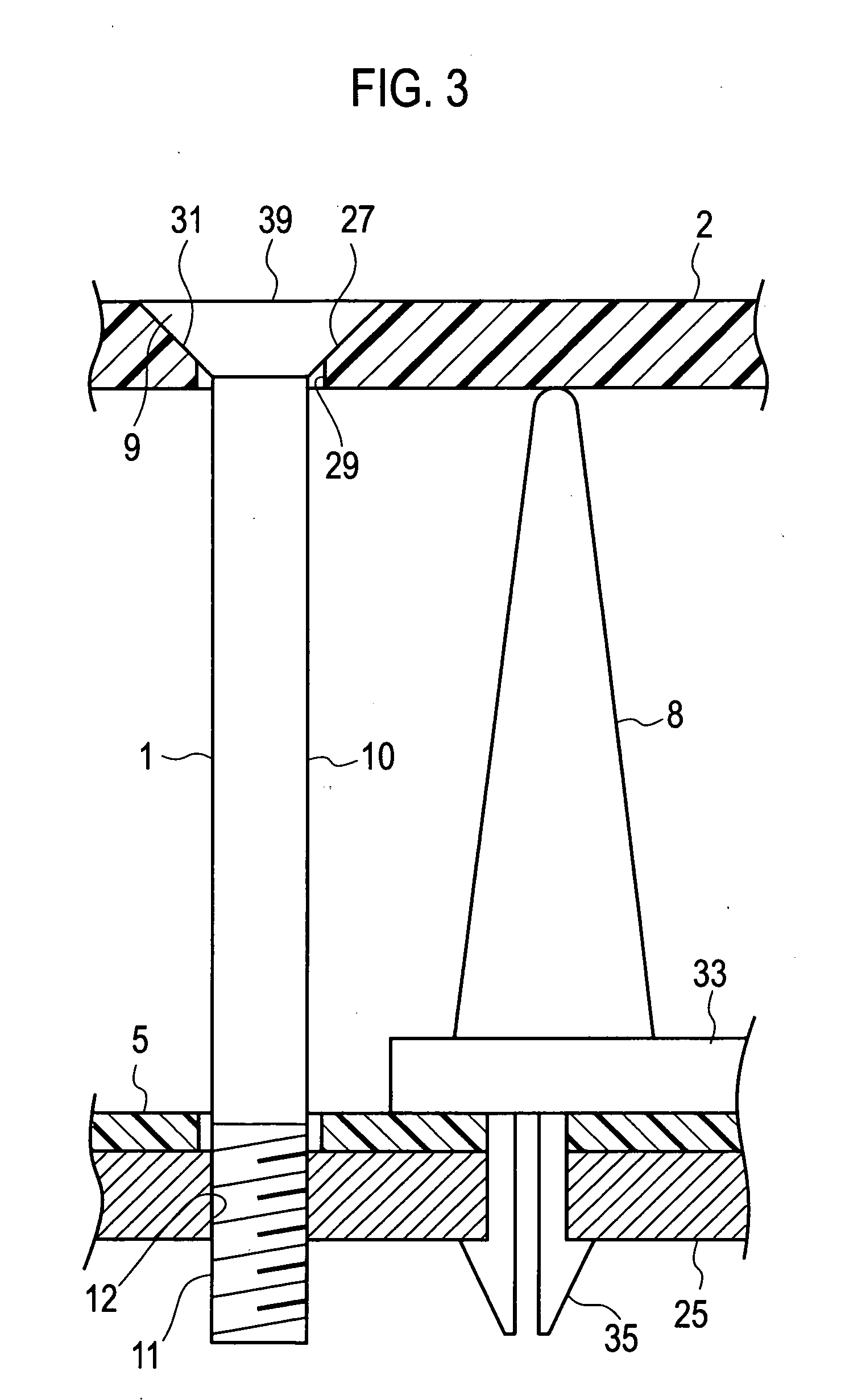
[0069]A liquid crystal display 21 includes optical sheets 6, a liquid crystal panel 7 and a backlight device 23. Each optical sheet 6 is composed of a polarized reflection film or the like and arranged in front of a diffuser plate 2 of the backlight device 23. The liquid crystal panel 7 is arranged in front of the optical sheets 6. Light emitted from the backlight device 23 passes though the diffuser plate 2 and the optical sheets 6 to illuminate the liquid crystal panel 7. The liquid crystal display 21 drives the liquid crystal panel 7 using a driving device or the like (not shown), and modulates light emitted from the backlight device 23 to carry out gradation process, which allows various images to be displayed thereon. It is noted that the upper side of FIG. 1 corresponds to a front side of the liquid crystal display 21 and the lower side of FIG. 1 corresponds to a rear side of the liquid crystal display 21.

[0070]The backlight device 23 includes fixing members 1, the diffuser pl...

second exemplary embodiment

[0105]A liquid crystal display 101 includes a liquid crystal panel 102 and a backlight device 103. The liquid crystal panel 102 is arranged as a display unit in the front of the liquid crystal display 101 (a viewed side, a display surface side, or a front side of the liquid crystal display 101). The backlight device 103 illuminates the liquid crystal panel 102. It is noted that the upper side of FIG. 7 corresponds to the front side of the liquid crystal display 101 and the lower side of FIG. 7 corresponds to a rear side of the liquid crystal display 101.

[0106]The backlight device 103 includes optical sheets 104, supporting members 105, a housing (open case) 1031, a diffuser plate 1032, a reflector sheet (reflector member) 1033, CCFLs 1034 and lamp holders 1035.

[0107]The housing 1031 has one open surface. The diffuser plate 1032 is a light diffuser plate for diffusing light emitted from the CCFLs 1034 and arranged on the one open surface to close the housing 1031. The diffuser plate ...


PUM

PropertyMeasurementUnit
thickaaaaaaaaaa
thickaaaaaaaaaa
thickaaaaaaaaaa

Abstract

A backlight device includes a housing, a light source, a diffuse plate and a fixing member. The housing has an open surface. The light source is arranged in the housing. The diffuser plate is arranged on the open surface of the housing and allows light emitted from the light source to pass therethrough while diffusing the light. The fixing member prevents the diffuser plate from bending in a direction in which light passes through the diffuser plate. A part of the fixing member has transmittance adjusted to substantially equalize luminance distribution of light passed through the diffuser plate.

Description

BACKGROUND OF THE INVENTION[0001]1. Field of the Invention[0002]The present invention relates to a backlight device and a liquid crystal display provided with the backlight device.[0003]2. Description of the Related Art[0004]As an apparatus for displaying an image or a video, a liquid crystal display (LCD) spreads widely. Recently, demands for enlarging a screen (liquid crystal panel) of a liquid crystal display and thinning a main body of liquid crystal display increase.[0005]Since a liquid crystal does not emit light by itself, the liquid crystal display displays an image using an emitting device (backlight device) arranged in back of the liquid crystal panel.[0006]As a light source used in the backlight device, a point light source such as a light emission diode (LED) or a line light source such as a cold cathode fluorescent lamp (CCFL) are cited generally.[0007]The backlight device is classified into an edge-light type, a just-below type or the like according to a position where...

Claims


Application Information

Patent Timeline
Patent Type & Authority Applications(United States)
IPC IPC(8): G02F1/1333G02F1/13357
CPCG02F1/133604G02F2201/54G02F1/133608G02F1/133606
Inventor SASAKI, TSUYOSHIOKUMURA, MIKIOKAMIYAMA, KOICHIASHIHARA, MAKOTO
Owner JVC KENWOOD CORP A CORP OF JAPAN
Why Eureka
Try Eureka